
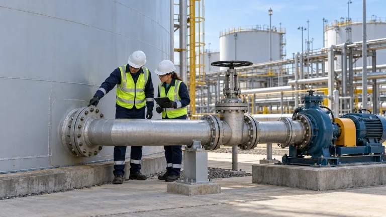
A storage tank can still contain a substantial volume of liquid when its transfer pump becomes unreliable. As the level falls, suction pressure drops, an outlet can draw in gas through a surface vortex, and settled water or solids can reach the transfer line. The practical minimum operating level is therefore a system limit: it depends on the tank outlet, the liquid, the suction line, the pump and the control response.
This guide focuses on an aboveground tank feeding an external rotodynamic transfer pump. Other pump types and tank arrangements need their own checks. The final setpoints must be established by the project engineer and equipment suppliers, using the actual operating envelope.
Start with the transfer duty and tank outlet
Identify the product range, density, viscosity, vapor pressure at the highest credible pumping temperature, normal and maximum transfer rates, and whether one or several pumps can run from the tank at the same time. Record the minimum and maximum pressure above the liquid, including credible vent or pressure-control conditions. A tank with a floating roof, nitrogen blanket or pressure-vacuum vent should not automatically be treated as an open atmospheric vessel.
On a common elevation datum, locate the tank bottom, outlet entrance, liquid-level instrument zero, pump NPSH datum, pipe high points and lowest expected level. Confirm whether the outlet is side-mounted, fitted with an internal suction device, or connected to a sump. Check liquid approach from tank inlets and recirculation lines: inlet jets and swirl can affect what reaches the outlet even when the measured level is stable.
Outlet elevation is a compromise. A lower pickup can improve inventory recovery but may draw accumulated water or sediment sooner. A raised pickup may leave more unusable inventory, yet reduce routine pickup of settled contamination. Neither arrangement removes the need for sampling, maintenance and a documented operating limit. For fuel service, see our separate guide to diesel tank water bottoms.
Check NPSH at the pump, not just at the tank
Net positive suction head available (NPSHA) expresses the liquid’s total absolute head at the pump NPSH datum above its vapor-pressure head. It is a property of the installed system and changes with level, surface pressure, temperature, flow and suction-side losses. NPSH required (NPSHR) comes from the pump supplier for a stated flow, speed and test criterion. The two must be compared at corresponding operating conditions, with a margin selected for the duty. The Hydraulic Institute pump fundamentals explains both quantities and why the common NPSH3 test point is not a guarantee of cavitation-free operation.
For a large, relatively still supply tank and a steady single-liquid centrifugal-pump calculation, a useful screening equation is:
NPSHA = (Psurface,abs – Pvapor,abs) / (ρg) + (zsurface – zpump datum) – hloss
Here pressure is absolute, ρ is liquid density, g is gravitational acceleration, elevations use the same datum, and hloss includes entrance, piping, valves, fittings and the relevant strainer condition. Express each term in metres of the pumped liquid. Confirm the manufacturer’s datum and calculation conventions. This simplified form does not capture every transient, two-phase condition or reciprocating-pump acceleration effect.
Illustrative screening calculation
Assume a hypothetical liquid with density 1,000 kg/m³ and vapor pressure 80 kPa absolute at the operating temperature. The tank surface pressure is 101.3 kPa absolute, the liquid surface is 1.2 m above the pump datum, and total suction losses at the evaluated flow are 1.0 m of liquid. Then the pressure contribution is approximately 2.17 m, giving NPSHA ≈ 2.17 + 1.2 – 1.0 = 2.37 m.
If a supplier’s NPSHR at that same duty is 2.0 m, the calculated difference is only about 0.37 m. Whether that margin is acceptable depends on the pump, liquid and reliability target; the example does not establish an acceptance threshold. A drop in level, lower tank surface pressure, hotter liquid or greater strainer loss can reduce the available head. Check the complete range of credible combinations rather than assuming that one convenient condition governs. The Hydraulic Institute’s NPSH margin guidance discusses the relationship between NPSHA, NPSHR and reliability.
Minimum submergence is a separate check
A mathematically adequate NPSHA does not by itself prove that the outlet will remain free of air-entraining vortices. Submergence is the liquid depth above a defined suction entrance reference; the appropriate reference depends on the device and geometry. Flow rate, entrance design, nearby walls, inlet jets and circulation affect vortex behavior. Submerged vortices can also disturb flow or cause localized cavitation, while leaks on the suction side may admit air.
Determine the required submergence for the actual outlet geometry and maximum simultaneous withdrawal with the designer and equipment supplier. Avoid applying a universal multiple of pipe diameter without checking its assumptions. More submergence, improved approach flow or a properly engineered anti-vortex device may help, but a plate or baffle added without hydraulic review can introduce obstruction, create a solids trap or impede access. KSB’s guidance on pump inlet conditions describes the effects of approach flow and the measures used against vortices.
Account for the entire suction path
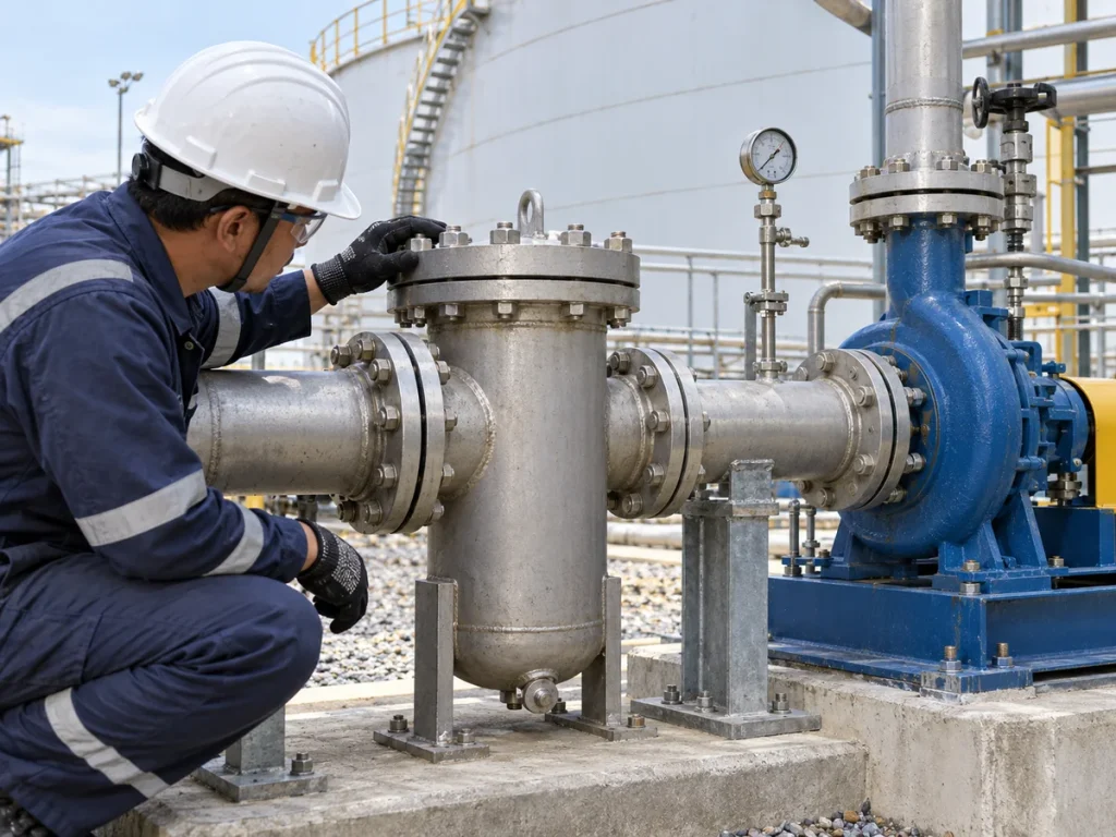
The line between tank and pump is part of the tank withdrawal design. Calculate losses at the maximum credible flow using the properties at operating temperature and the actual arrangement of entrances, elbows, valves, reducers, strainers and common headers. Assess both pumps running where parallel operation is possible. A clean commissioning strainer and a strainer approaching its maintenance limit are different cases; establish an allowable differential-pressure limit and access for cleaning.
Avoid unnecessary restrictions and trapped high points, and coordinate the manufacturer’s suction-piping arrangement and straight-run requirements. A suction line may operate below atmospheric pressure, so small leaks can admit air without showing an obvious liquid leak. Check isolation valve position, gaskets, vents and any temporary commissioning screens. A pressure gauge near the pump and differential-pressure monitoring across a strainer can help diagnose developing restrictions, provided instruments are suitable for the fluid and hazardous-area classification.
Vibration, noise, fluctuating flow or loss of prime can result from cavitation, gas entrainment, blocked suction, mechanical problems or other causes. Do not diagnose from one symptom alone. Compare tank level, temperature, surface pressure, suction pressure, strainer differential pressure and pump operating point before deciding on a corrective action. The Hydraulic Institute pump FAQ lists the system variables that affect NPSHA.
Turn the hydraulic limit into usable alarm and trip levels
Evaluate the minimum liquid level needed for each constraint on the same level reference: NPSH margin at the relevant duty, submergence, product quality and any equipment-specific minimum. The controlling limit is the highest applicable level, after engineering review. Translate it into the level instrument’s datum and tank capacity table; account for instrument accuracy, calibration, sloshing or process fluctuations, and the response and stopping time of the pump and controls.
Set a low-level alarm early enough for an operator to respond, and a low-low shutdown or other protective action where the hazard assessment requires it. Confirm whether a running pump should stop, whether a standby pump can start, how restart is prevented, and how alarms are handled if the level instrument fails or communications are lost. Establish operating procedures for safe shutdown and restart; never rely on a low-level switch alone to compensate for an unsuitable suction design. Our tank calibration and capacity-table guide explains why the level datum and volume relationship need document control.
Commissioning and handover checks
- Confirm the as-built outlet, suction line, supports, strainers and pump elevations against the approved drawings and calculations.
- Verify vent or blanketing operation and establish the permitted surface-pressure range during withdrawal.
- Clean and inspect the suction path, identify temporary screens and agree when and how they will be removed.
- Test level indication, alarm, pump shutdown and restart logic using the approved procedure and an appropriately controlled test method.
- Record pump flow, suction pressure, product temperature, tank level and strainer differential pressure at agreed operating points.
- Hand over the calculations, pump curves, instrument setpoints, alarm response, inspection access and residual-volume assumptions.
When modifications change the outlet, pump, stored product, level measurement or operating flow, review the limits before returning to service. The suction connection also imposes loads and maintenance interfaces on the tank; see our guide to tank nozzles, pipe supports and access.
Practical takeaway: specify the minimum operating level as a verified system constraint. A useful design combines adequate NPSH margin, outlet submergence, acceptable product quality and controls that act before the system crosses its limit.