
Tank nozzles, pipe supports, access platforms, and instrumentation connections look like detailed engineering items, but they can create major EPC interface problems when they are decided too late. A storage tank may be structurally sound and correctly sized, yet still become difficult to install, operate, or maintain because the pipe routing, nozzle orientation, support spacing, or access clearance was not coordinated early.
This article builds on the broader industrial storage tank selection process. Once capacity, material, foundation, and containment assumptions are known, the project team should move quickly into interface review. The goal is to make sure the tank can be connected to the plant safely and maintained after commissioning.
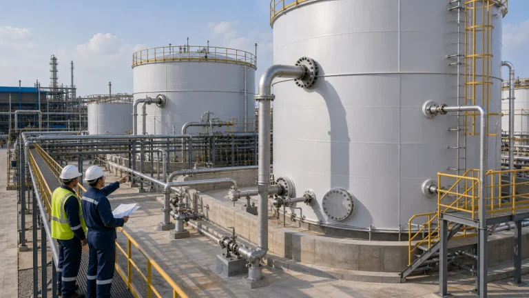
Why Tank Interfaces Cause EPC Problems
Tank suppliers often focus on the tank shell, roof, bottom, nozzles, manways, platforms, and basic accessories. Piping teams focus on process routing, valves, pipe stress, pump connections, and rack layout. Civil teams focus on foundation, containment, drainage, and access. Operations teams care about inspection, cleaning, sampling, instrument maintenance, and emergency isolation. If these views are not merged, the tank interface becomes a conflict point.
Common problems include a nozzle facing the wrong direction, a pipe support landing inside a drainage path, a manway blocked by a platform member, an instrument mounted too high for safe maintenance, a valve wheel too close to a handrail, or rigid piping transferring load into the tank shell. These are not unusual design defects. They are normal interface risks when layout review is too shallow.
1. Freeze Nozzle Orientation Only After Layout Review
Nozzle orientation should be reviewed against the actual plant layout, not only the tank general arrangement drawing. The team should check pipe rack direction, pump skid location, valve access, containment wall position, road clearance, crane access, platform locations, manway swing, and future expansion space.
A nozzle that looks acceptable on a vendor drawing may create an awkward pipe route in the field. Long pipe runs, unnecessary elbows, blocked walkways, difficult valve access, or high pipe stress can result from a small orientation error. For large tanks, changing nozzle orientation late can affect fabrication, coating, testing, and delivery schedule.
2. Do Not Let Piping Loads Become Tank Loads
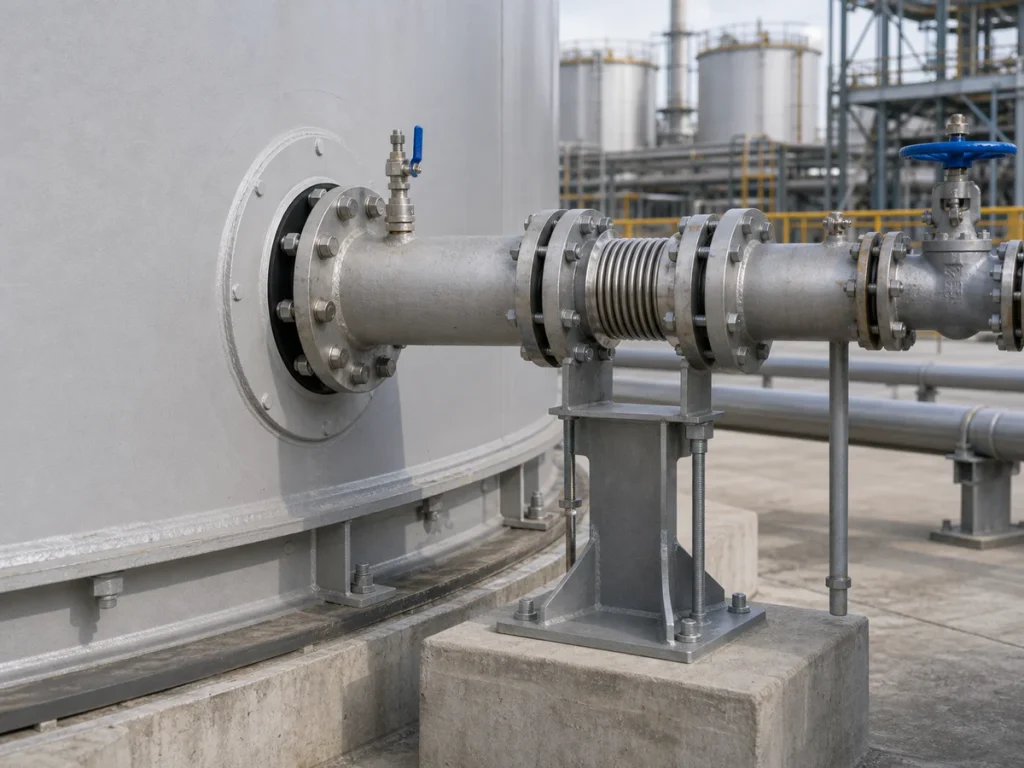
Tank nozzles are not designed to carry unlimited piping loads. Rigid pipework, poor support spacing, thermal expansion, pump vibration, settlement, and misalignment can all transfer forces and moments to the tank shell. Over time, this can contribute to flange leakage, shell distortion, nozzle cracking, coating damage, or maintenance difficulty.
The piping team should review nozzle loads, support locations, guide and anchor strategy, expansion loops, flexible connections, and installation tolerance. The first support near a tank nozzle is especially important. It should help control pipe weight and movement without forcing the tank nozzle to act as a structural support.
Foundation settlement can also affect piping alignment. This is why pipe support and nozzle design should be reviewed together with storage tank foundation design, especially for large tanks, soft soil sites, or tank farms with rigid pipe racks.
3. Plan Pipe Supports Before Civil Work Is Frozen
Pipe supports need real locations, not placeholders. If support pedestals, embedded plates, trenches, containment slopes, drains, or pipe rack columns are finalized before pipe support loads are reviewed, the site may need field modifications later. Those modifications can affect concrete quality, drainage, coating repair, and installation schedule.
Support planning should confirm pipe size, material, insulation, operating temperature, filled weight, thermal movement, valve weight, support type, and whether support reactions affect containment or foundation details. For outdoor tank farms, supports should also avoid creating trip hazards or blocking inspection routes.
4. Keep Valves Reachable and Operable
A valve that is technically installed but hard to reach is a future operating problem. Valve wheel height, hand clearance, platform access, emergency isolation route, and visibility should be reviewed before the layout is approved. Operators should not need temporary ladders, unsafe reaching, or awkward body positions for routine operation.
Heavy valves may also need independent support. If a large valve is hung from a nozzle without proper pipe support, the tank connection may see unnecessary bending load. Valve maintenance should also be considered: can the valve be removed without cutting pipe, dismantling a platform, or blocking another operating area?
5. Design Instrument Connections for Maintenance
Level transmitters, pressure instruments, temperature points, sampling connections, overflow indicators, vent devices, and alarms require maintenance access. Instrument drawings should be reviewed against platforms, ladders, cable trays, lighting, and safe working space.
Instrumentation should also match the process. A level instrument suitable for clean water may not perform well in sludge, foam, viscous liquids, floating scum, crystallizing chemicals, or high-vapor service. The tank connection, stilling well, isolation valve, calibration access, and cleaning method should be selected together.
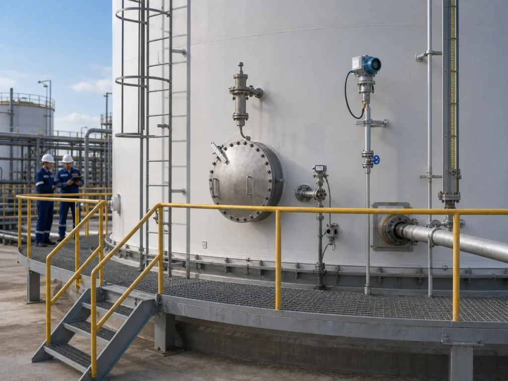
6. Manways and Cleaning Access Need Working Space
Manways are often shown on drawings but not fully checked for field access. The team should confirm cover swing, bolt removal, gasket replacement, lifting assistance, cleaning equipment access, internal inspection entry, and ventilation setup. If a manway is too close to a wall, platform column, pipe rack, or containment curb, it may be technically present but practically unusable.
Cleaning method matters. A tank that requires periodic sludge removal, chemical cleaning, high-pressure washing, or internal inspection should have access points and drainage arrangements that match those tasks. Designers should avoid placing cleaning access where operators cannot safely stage hoses, pumps, tools, or temporary ventilation equipment.
7. Coordinate Access Platforms With Nozzles and Instruments
Platforms should support real work, not only satisfy a drawing requirement. A good access platform gives operators room to stand, open valves, remove instruments, inspect flanges, check vents, and move safely around obstructions. It should also avoid blocking nozzles, lifting routes, manway covers, or pipe installation paths.
Handrails, toe plates, ladder cages, stair orientation, platform elevation, and lighting should be checked in the same model or layout review as the tank nozzles. If platforms are designed after nozzles and piping are fixed, the platform may become a compromise rather than a safe maintenance surface.
8. Review Containment and Drainage Interfaces
Tank piping often crosses containment boundaries or passes near drainage channels. Pipe supports, valve stations, nozzle drains, sample points, and pump connections should be reviewed against containment wall height, sump location, floor slope, rainwater route, and emergency response space.
This connects directly with secondary containment design for industrial storage tanks. A pipe penetration through a bund wall, for example, must be sealed and supported. A drain valve should not discharge outside a controlled route. A support pedestal should not create a dead pocket where leaked liquid accumulates unseen.
9. Use Vendor Drawings as Interface Documents
Tank vendor drawings should not be treated as isolated fabrication documents. They should become interface documents for civil, piping, electrical, instrumentation, operations, and safety review. The review should include nozzle schedule, orientation plan, elevation, flange rating, platform layout, ladder arrangement, manway location, vent details, overflow route, drain point, and foundation anchor information.
A useful approval process asks specific questions: Can the pipe route be built? Can the supports be installed? Can the valve be operated? Can the instrument be calibrated? Can the manway be opened? Can the containment system still function? Can the tank be inspected and cleaned without unsafe temporary work?
EPC Interface Checklist
- Review nozzle orientation against plant layout, pipe racks, pumps, platforms, containment walls, and access routes.
- Confirm allowable nozzle loads and coordinate pipe stress assumptions with tank vendor data.
- Place the first pipe supports near tank nozzles early enough for civil coordination.
- Check flexible connections, expansion loops, guides, anchors, and settlement movement where required.
- Make valves reachable, visible, operable, and maintainable without unsafe temporary access.
- Confirm instrument access for calibration, cleaning, removal, cable routing, and isolation.
- Verify manway clearance, cover swing, bolt access, cleaning access, and internal inspection needs.
- Coordinate pipe penetrations, drains, and support pedestals with containment and drainage design.
- Use vendor drawings as multidisciplinary interface documents before releasing them for fabrication.
Common Mistakes to Avoid
The most common mistake is approving tank vendor drawings before piping and operations teams have reviewed real access. Another is assuming that pipe stress can be solved later, after nozzle orientation and support locations are already fixed. Teams also underestimate small details such as valve handwheel clearance, instrument removal space, and manway cover swing.
A tank connection is not successful just because the pipe can be drawn to it. It must be buildable, supportable, inspectable, operable, and maintainable. That requires interface review before fabrication and civil work are too far advanced.
Conclusion
Tank nozzle, pipe support, and access design are practical EPC coordination issues. They sit between vendor design, piping layout, civil foundations, containment design, instrumentation, and operations. When these interfaces are reviewed early, the project avoids field rework and gives operators a safer, more maintainable tank system.
The best tank layout is not only one that fits on a drawing. It is one that can be connected, supported, inspected, cleaned, and operated throughout the life of the facility.