
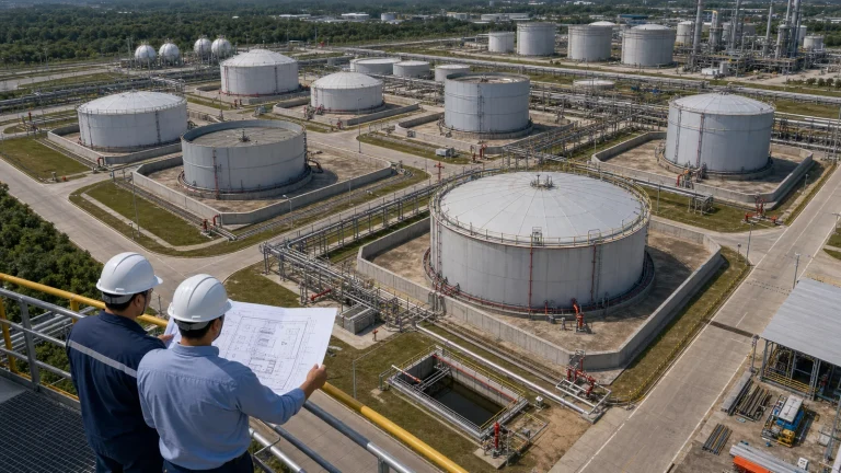
Tank farm layout design is where storage capacity becomes an operating facility. A drawing may show the right number of tanks and the correct total volume, but the tank farm will still fail in practice if spacing, containment, roads, drainage, firefighting access, pipe racks, maintenance clearance, truck movement, and future expansion are not coordinated. Layout is not a cosmetic arrangement of circles on a plot plan; it is an engineering decision that affects safety, operability, environmental control, and lifecycle cost.
For EPC teams, the best tank farm layout is developed from stored liquid properties, tank size, code requirements, fire protection strategy, spill control, site topography, prevailing wind, construction method, inspection access, and owner operating procedures. The earlier these interfaces are reviewed, the fewer late-stage conflicts appear around foundations, roads, pipe racks, drains, hydrants, and platforms.
Start With Stored Liquid and Hazard Grouping
The first layout decision is what is being stored. Water, wastewater, fire water, process liquids, acids, caustic, oils, solvents, fuels, volatile organic liquids, and slurries do not belong in the same planning category. The stored liquid influences tank spacing, containment volume, fire protection, drainage routing, material compatibility, odor or vapor control, vehicle access, and emergency isolation.
Where liquids are incompatible, the layout should prevent one failure from creating a second chemical, fire, or environmental problem. Acid and caustic tanks may need separation, dedicated drainage, corrosion-resistant containment, and independent unloading areas. Flammable liquids may require larger separation distances, ignition source control, foam systems, classified electrical areas, and emergency access from multiple directions.
1. Tank Spacing Is More Than a Minimum Number
Tank spacing must satisfy applicable codes, local authority requirements, owner standards, firefighting access, construction access, settlement monitoring, inspection routes, piping flexibility, and maintenance clearance. OSHA’s flammable liquid rules include minimum shell-to-shell spacing requirements for above-ground tanks and require greater spacing or other means when tanks are arranged so inside tanks need firefighting access. Those numbers are a regulatory baseline, not a complete layout philosophy for every industrial service.
Practical spacing should also consider tank diameter, height, roof type, insulation, ladders, platforms, mixers, nozzles, foam chambers, vents, thermal radiation, wind direction, and crane reach. Two tanks may meet a minimum spacing rule yet still be difficult to inspect, repaint, repair, or reach with firefighting equipment.
2. Group Tanks by Service, Risk and Operation
Grouping similar tanks can simplify piping, containment, fire protection, operation, and maintenance. Fire water tanks may sit near pump houses and ring mains. Process water tanks may sit closer to production users. Chemical storage may need dedicated unloading, eyewash and shower access, corrosion-resistant containment, and clear traffic separation. Fuel or solvent tanks may need separation from nonhazardous utility tanks and occupied buildings.
Grouping should not create operational congestion. Operators need room to read instruments, operate valves, take samples, inspect vents, reach platforms, remove pumps, and respond to abnormal conditions. A layout that minimizes pipe length but blocks people and vehicles will create daily operating risk.
3. Secondary Containment Defines the Real Footprint
Tank farm layout is often constrained by secondary containment rather than tank shell diameter. EPA SPCC guidance for regulated oil facilities requires bulk storage installations to provide secondary containment for the capacity of the largest single container and sufficient freeboard for precipitation. Even outside that exact regulatory context, the engineering principle remains important: a tank farm should be laid out so a credible release can be contained and managed.
Containment walls, bunds, curbs, liners, floor slopes, sumps, pipe penetrations, stairs, ramps, and drain valves must be coordinated as one system. The broader issues discussed in secondary containment for industrial storage tanks become layout issues as soon as roads, pipe racks, and access platforms cross the containment boundary.
4. Drainage Must Distinguish Clean and Contaminated Water
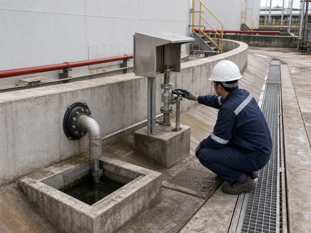
A tank farm sees rainwater, washdown water, hydrotest water, firewater runoff, small leaks, unloading spills, and possibly contaminated process liquid. The layout should define where each stream goes. Clean stormwater should not be routed through areas likely to collect oil or chemicals if that can be avoided. Potentially contaminated water should be held, sampled, treated, or intentionally released only through controlled procedures.
Drain valves through containment walls should normally be managed with clear operating rules. A normally open drain can defeat containment. A normally closed drain without inspection can flood the bund during rain. Sloped paving, sump capacity, drain elevation, valve access, freeze protection, and safe operator approach all affect whether the drainage plan works in bad weather.
5. Roads and Emergency Access Need Turning Space
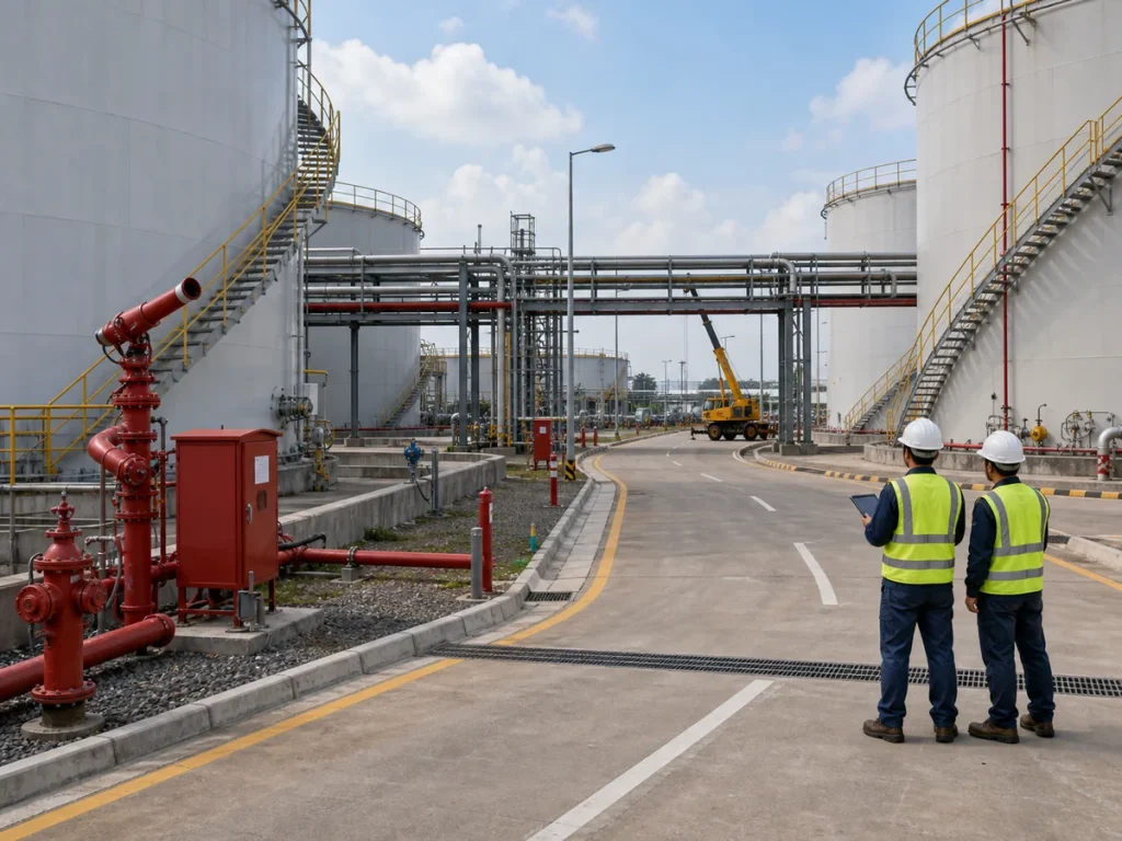
Roads inside and around a tank farm are not only for construction. They serve emergency response, maintenance vehicles, vacuum trucks, chemical deliveries, crane access, inspection teams, and routine operations. The layout should provide practical approach routes, turning radii, road width, load rating, overhead clearance, and alternative access if one route is blocked.
For larger tank farms, dead-end roads and narrow corridors should be challenged early. Fire trucks, foam trailers, cranes, forklifts, vacuum trucks, and tank cleaning equipment all have different space needs. A road shown as a line on the plot plan may be useless if pipe racks, hydrants, stairs, or drainage channels reduce usable width.
6. Fire Protection Should Shape the Plot Plan
Firewater mains, hydrants, monitors, foam systems, deluge valves, detection, emergency isolation, access gates, and safe response positions should be integrated before the plot plan is frozen. Retrofitting foam chambers, monitor locations, hydrant spacing, or firewater ring mains after foundations and roads are complete can be expensive and disruptive.
Tank roof design also affects fire response. Fixed roof tanks, external floating roof tanks, internal floating roof tanks, dome roof tanks, vents, foam chambers, rim seal systems, and emergency vents all create different access and response needs. The layout should therefore align with the tank’s roof design and venting strategy, not treat fire protection as a separate discipline.
7. Pipe Racks Should Not Block People or Fire Access
Pipe racks can make a tank farm compact, but they can also block sight lines, restrict emergency access, create low-point drainage conflicts, and make maintenance difficult. Pipe rack routing should consider road crossings, minimum overhead clearance, expansion loops, thermal movement, valve access, pipe supports, fireproofing, drainage, and future lines.
The location of manifolds, pumps, meters, sample points, and isolation valves should allow operators to work safely without standing in traffic lanes, climbing over bund walls, or reaching across hot or hazardous lines. Pipe support and nozzle loads must also be controlled; the issues discussed in tank nozzle, pipe support and access design become more visible when multiple tanks share a congested pipe rack.
8. Loading, Unloading and Transfer Areas
A tank farm often includes truck unloading, rail unloading, tanker transfer, drum filling, tote handling, or chemical dosing connections. These areas need spill containment, vehicle approach, hose handling, grounding and bonding where required, sampling points, emergency showers, lighting, operator shelter, communication, and traffic separation.
Unloading areas should not be squeezed into leftover space. A poorly located unloading station can block emergency access, force hoses across roads, mix incompatible chemicals, or route spills toward clean stormwater drains. The layout should define where vehicles stop, how they turn, where hoses connect, and where spilled liquid will go.
9. Maintenance and Inspection Clearance
Tanks require inspection, coating repair, nozzle work, roof access, mixer removal, vent maintenance, valve replacement, cleaning, sludge removal, and sometimes panel or shell repair. Layout should reserve space for cranes, manlifts, scaffolding, temporary ventilation, tank cleaning equipment, vacuum trucks, hydrotest pumps, and laydown of removed parts.
Maintenance clearance should be checked around each tank, not only at the perimeter. If an inside tank cannot be reached without crossing multiple bund walls and pipe racks, maintenance will be delayed or performed in less safe ways. Future recoating and internal lining work also need ventilation duct routes, electrical supply, and safe entry control areas.
10. Elevation, Settlement and Grading
Site grading affects containment, drainage, foundation performance, vehicle movement, and construction sequencing. Tanks should not be placed where surface water naturally collects unless the civil design controls that risk. Foundations need stable subgrade, settlement monitoring access, and drainage around the ringwall or slab.
Elevation differences can help drainage, but they can also complicate pipe stress, pump suction, containment wall height, stair access, and emergency response. EPC teams should review topographic survey, geotechnical data, stormwater design, pipe routing, and construction drainage together rather than treating grading as a late civil adjustment.
11. Utilities, Instruments and Electrical Areas
Power supply, grounding, lighting, CCTV, gas detection, level instruments, overfill alarms, valve actuators, heat tracing, cathodic protection, communication, and control cabinets all occupy layout space. In flammable service, electrical classification and ignition source control can influence where equipment, cable trays, motors, and buildings are located.
Instrument access matters. Level transmitters, radar gauges, temperature probes, pressure-vacuum vents, overfill devices, and local indicators should be reachable without special scaffolding whenever possible. Poor layout creates maintenance blind spots and weakens inspection discipline.
12. Future Expansion and Decommissioning
Many tank farms expand over time. The first phase should leave realistic space for future tanks, pipe rack extension, additional pumps, larger containment, more firewater demand, extra roads, and electrical capacity. Future expansion space should not become a temporary storage yard that later blocks the project.
Decommissioning should also be considered. Eventually tanks may need cleaning, product removal, sludge disposal, cutting, lifting, or replacement. If the layout makes removal impossible without shutting down the whole facility, the owner will pay for that decision later.
Tank Farm Layout EPC Checklist
- Classify stored liquids by hazard, compatibility, volatility, corrosion, environmental risk, and operating requirements.
- Confirm applicable codes, local authority requirements, owner standards, insurance requirements, and fire protection philosophy.
- Set tank spacing for code compliance, firefighting access, inspection, maintenance, piping flexibility, and future modifications.
- Design secondary containment for credible release volume, precipitation freeboard, drainage control, pipe penetrations, and safe access.
- Separate clean stormwater from potentially contaminated drainage wherever practical.
- Provide roads with turning radius, load rating, overhead clearance, alternative access, and maintenance vehicle space.
- Coordinate hydrants, foam monitors, firewater mains, emergency gates, detection, and safe response positions with the plot plan.
- Route pipe racks without blocking roads, drains, valve access, settlement monitoring, or emergency approach routes.
- Plan unloading areas for spill control, vehicle movement, hose handling, operator safety, and traffic separation.
- Reserve crane, manlift, vacuum truck, scaffold, ventilation, and laydown space for maintenance and inspection.
- Review grading, foundations, stormwater, containment walls, and road elevations together.
- Leave realistic space and utility capacity for future tanks and decommissioning work.
Common Mistakes to Avoid
The first mistake is optimizing pipe length while ignoring emergency access and maintenance clearance. The second is sizing containment volume without checking how rainwater will be managed. The third is placing unloading stations, pumps, or manifolds in leftover spaces where vehicles, hoses, drains, and operators conflict.
Another common mistake is treating fire protection as a later discipline. Firewater, foam, access roads, monitors, and safe response positions need space. If that space is not reserved early, the final layout may technically store liquid but remain difficult to protect and maintain.
Conclusion
Tank farm layout design is a system-level EPC decision. It connects storage capacity, tank spacing, containment, drainage, roads, pipe racks, unloading areas, fire protection, maintenance access, inspection routes, utilities, grading, and future expansion.
A good layout does not simply fit tanks into a boundary. It creates a facility that operators can run, inspectors can access, firefighters can approach, maintenance teams can repair, and owners can expand without redesigning the whole site. That is why tank farm layout should be resolved early, before foundations, pipe racks, roads, and containment walls make the wrong decisions permanent.