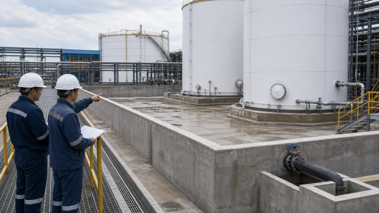
Secondary containment is one of the most visible parts of an industrial tank farm, but it is often under-discussed during early planning. A concrete bund, containment wall, curb, sump, or drainage valve is not just a civil accessory. It is part of the risk-control system that determines how the site responds to leaks, rainwater, washdown, firefighting water, and maintenance activity.
In an earlier article, we discussed broad industrial storage tank selection. Once tank type, material, capacity, and foundation assumptions start to take shape, the containment layout should be reviewed at the same time. Waiting until the tank arrangement is already frozen can create poor drainage, unsafe access, difficult pipe routing, or insufficient emergency response space.
What Secondary Containment Is Supposed to Do
Secondary containment is designed to limit the movement of liquid if a tank, nozzle, valve, drain, pipe connection, or transfer operation fails. It may also help control contaminated rainwater or washdown water until operators can inspect and release it. The exact design basis depends on the stored liquid, local regulations, site risk assessment, tank arrangement, and operating procedures.
For hazardous chemicals, fuel, leachate, wastewater, acidic or alkaline solutions, and process liquids, the containment area should be evaluated as a system. Wall height alone is not enough. Engineers must consider floor slope, sump position, drain control, penetrations, pipe supports, operator access, tank spacing, firefighting access, inspection visibility, and whether the containment material is compatible with the liquid.
Capacity Is Only the Starting Point
Many teams first ask how much containment volume is required. That is important, but it is only one part of the design. The required volume may depend on the largest tank, grouped tanks, rainfall allowance, firefighting water, freeboard, displacement by tank foundations, and local environmental requirements. The project team should confirm the applicable requirement for the site instead of relying on a generic percentage rule.
Even when the calculated volume is adequate, the layout can still fail operationally. If the floor is flat, liquid may not reach the sump. If the drain valve is normally left open, containment can be bypassed. If piping penetrations are not sealed, a leak path may exist through the wall. If the containment is hard to inspect, small leaks may go unnoticed until they become larger problems.
Bund Layout Should Follow Real Leak Paths
A containment wall should be placed around the areas where liquid can realistically escape. That includes tank shells, lower nozzles, drain valves, transfer pumps, flexible connections, loading points, and pipe flanges inside the containment boundary. A neat rectangle on a drawing is not always the safest layout if the highest-risk equipment sits outside it.
Designers should review expected leak paths under gravity. Where would liquid flow from a tank bottom drain? What happens if a pump seal leaks? Does a nozzle leak flow toward the sump, toward an access route, or toward a wall penetration? Does the tank foundation curb block flow and create stagnant pockets? These questions should be answered before civil works are released for construction.
Foundation and Containment Need to Be Coordinated
The tank foundation and secondary containment often compete for the same elevations. The foundation must support the tank and control settlement, while the containment floor must direct liquid to a collection point. If these are designed separately, the result can be awkward slopes, inaccessible drains, poor anchor access, or pipe elevations that do not match the plant layout.
This is why containment should be reviewed together with above-ground storage tank foundation design. Ring foundations, anchor bolts, access steps, sump locations, drain channels, and containment wall openings should be coordinated as one field installation package.
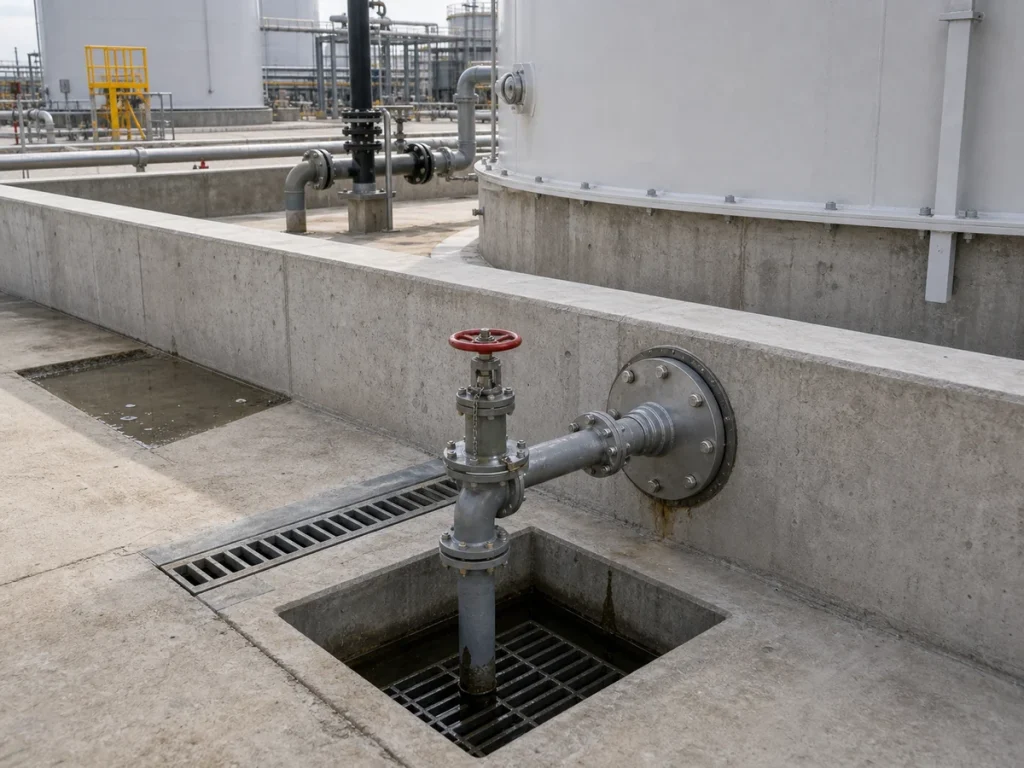
Drainage Valves Are Operational Controls, Not Just Fittings
Outdoor containment areas collect rainwater. Operators need a way to remove clean rainwater after inspection, but the same drain can become a bypass route during a leak if it is left open or poorly controlled. For this reason, containment drain valves should be clearly accessible, normally controlled, and included in operating procedures.
A practical design should define who can open the drain, how water is inspected before release, where the water goes, and what happens during rainfall when the tank area is unattended. Depending on the stored liquid, drainage may need to pass through an oily water system, wastewater treatment system, neutralization system, or dedicated collection tank rather than direct discharge.
Pipe Penetrations Are Common Weak Points
Pipe penetrations through containment walls deserve careful attention. Every penetration can become a leak path if it is not sealed, sleeved, supported, and inspected properly. Movement from thermal expansion, settlement, vibration, or pipe stress can also damage seal details over time.
Where possible, designers should reduce unnecessary wall penetrations and route pipework over containment walls using supports that do not compromise the containment boundary. When penetrations are unavoidable, the sealing method, chemical compatibility, fire requirement, inspection access, and repair method should be reviewed before construction.
Containment Material Must Match the Stored Liquid
Concrete containment is common, but untreated concrete may not resist all stored liquids. Acids, alkalis, solvents, salts, oils, and aggressive wastewater can attack concrete, joints, sealants, coatings, or embedded steel. A containment system may therefore require chemical-resistant lining, coating, joint sealant, or a different construction material.
The compatibility review should not stop at the tank shell. It should include containment floor coating, wall lining, sump materials, drain piping, valve seals, pipe penetration seals, and repair products. This connects directly with tank system decisions discussed in our guide to tank material selection.
Access and Inspection Should Be Designed In
Containment areas must be inspected, cleaned, and maintained. Operators need safe routes to valves, drains, sampling points, level instruments, manways, and emergency equipment. If containment walls are high, stairs, platforms, handrails, and safe egress routes may be needed. If the floor can become slippery, drainage and surface finish become safety issues as well as environmental issues.
Inspection access should include low points and hidden corners. Areas behind tanks, under pipe racks, near pump skids, and around wall penetrations are often where small leaks first appear. The layout should make those areas visible and reachable without unsafe climbing or entering confined spaces unnecessarily.
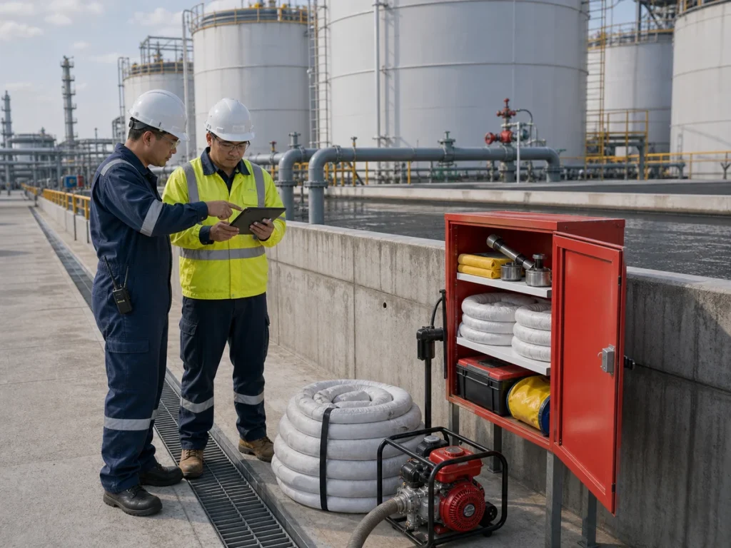
Emergency Readiness Is Part of the Design
Secondary containment does not eliminate the need for response planning. It gives the site time and space to respond. The project should define spill kits, temporary pumps, absorbents, neutralization materials where appropriate, isolation valves, emergency access, lighting, communication procedures, and trained personnel responsibilities.
Emergency equipment should be located where operators can reach it quickly, but not where it would be blocked by a realistic leak scenario. Site drills and inspection routines should verify that the equipment is complete, dry, accessible, and suitable for the chemicals stored in the tank area.
EPC Coordination Checklist
- Confirm the containment design basis, including applicable local requirements, stored liquid properties, rainfall assumptions, and response strategy.
- Review containment volume together with tank foundations, displacement, floor slope, freeboard, and sump geometry.
- Map realistic leak paths from tanks, pumps, valves, drains, nozzles, pipe flanges, and transfer points.
- Keep drain valves controlled, accessible, and included in operating procedures.
- Seal and support pipe penetrations so they do not become uncontrolled leak paths.
- Check chemical compatibility of floor coatings, wall linings, joint sealants, sumps, valves, and drain piping.
- Provide safe access for inspection, sampling, cleaning, valve operation, and emergency response.
- Coordinate civil, mechanical, environmental, and operations teams before IFC drawings are issued.
Common Mistakes to Avoid
One common mistake is designing containment only around tank shell volume while ignoring pump skids, loading areas, drain points, and pipe penetrations. Another is treating rainwater as an afterthought. If rainwater handling is unclear, operators may be tempted to leave drains open, which defeats the purpose of containment.
It is also risky to assume that concrete is always chemically suitable. For aggressive liquids, the containment system may need lining, coating, or special joint details. Finally, emergency response equipment should not be added only after commissioning. It should be part of the layout review, because response access depends on civil and mechanical design choices.
Conclusion
Secondary containment for industrial storage tanks is a system-level design issue. Bund walls, floor slopes, drainage valves, sumps, pipe penetrations, access routes, material compatibility, and emergency procedures all affect whether the site can control a leak safely.
A good containment layout is not only about holding volume. It is about directing liquid, preventing bypass paths, supporting operator decisions, and making inspection and response practical throughout the life of the tank farm.