
An industrial storage tank rarely overfills because of one failed component alone. The event is normally a chain: the wrong tank is selected, the available space is misunderstood, a level device is inaccurate, an alarm is missed, an operator cannot act in time, a valve does not close, or the transfer continues after the warning. Good overfill prevention breaks that chain early, with clear operating limits and more than one dependable layer of protection.
For owners, EPC contractors, and operations teams, the important question is not simply whether a tank has a level gauge. It is whether the entire receiving operation can reliably stop before liquid reaches a hazardous level. That includes tank capacity data, level instruments, alarm setpoints, response time, independent shutdown functions, transfer pumps and valves, communications, test procedures, emergency planning, and trained people.
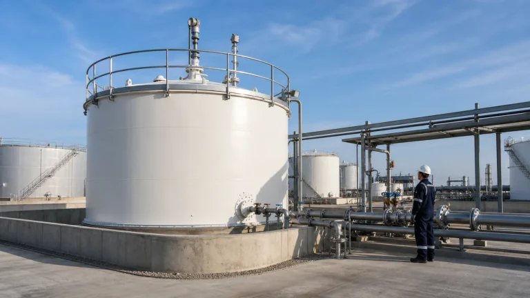
What Overfill Prevention Is Designed to Do
Overfill prevention is intended to receive product into the intended tank without loss of containment. The exact design requirements depend on the liquid, tank type, jurisdiction, facility risk assessment, and applicable standards. API Standard 2350 is a leading reference for above-ground petroleum storage tanks in specified petroleum services, but its scope should not be copied uncritically to every chemical, water, food, wastewater, or process storage tank. Each facility still needs a service-specific engineering and regulatory review.
The underlying engineering principle is widely useful: prevent the liquid level from reaching the point where the tank, roof, venting system, containment, or transfer arrangement can no longer control the inventory. Prevention is stronger than relying on a bund wall to manage a release after it has happened.
Start With Real Usable Capacity, Not Nameplate Volume
Nameplate capacity is not automatically the amount that can be safely received. The usable receiving volume depends on tank geometry, calibration data, product temperature, operating inventory, roof configuration, required freeboard, level measurement accuracy, foam or vapor behavior, mixing, and the time needed to stop incoming flow. A tank may be near its working high level long before it is geometrically full.
Before every transfer, the operator needs a trustworthy answer to three questions: which tank will receive the material, how much verified space is available, and how long it will take to reach each alarm or trip point at the expected flow rate. A manual dip, inventory system, radar gauge, or control-room display can support this decision, but it must be reconciled with the current operating condition. Product in a common manifold, a valve lineup error, a tank under maintenance, or a transfer already in progress can invalidate an otherwise correct calculation.
Use Clear Operating Levels
A practical design distinguishes several levels rather than treating every high indication as the same event. Terminology varies by site, but the logic normally includes a normal operating range, a high level warning, a high-high protective level, and a maximum safe level or physical limit. The setpoints must leave enough volume and time between them for the intended response.
The high alarm should give the operations team a meaningful early warning. It might trigger a control-room alarm, request transfer reduction, and require confirmation of tank identity and remaining space. The high-high signal is normally reserved for a more urgent response, such as automatically stopping an inlet pump, closing an inlet valve, stopping an upstream transfer, or initiating a clearly defined immediate operator action. A high-high setpoint that occurs too close to the overfill point is not a useful protective layer.
Primary Level Measurement: Accurate Enough for Inventory and Control
Continuous level instruments commonly include radar, servo, guided-wave radar, pressure or differential-pressure methods, and other technologies suited to the tank and liquid. Selection should consider vapor, foam, density, dielectric properties, temperature, pressure, corrosion, nozzle geometry, roof movement, internal obstructions, electrical classification, maintenance access, and the required accuracy.
The primary instrument is often used for inventory, trend display, transfer control, and the high alarm. It should be maintainable without creating an unnecessary operating risk. Cable routing, grounding, instrument isolation, calibration access, local indication, and platform access should be resolved in the EPC design, not added informally after handover. The same applies to roof penetrations and access; they need to work with the tank’s roof design, vents, and drainage arrangements.
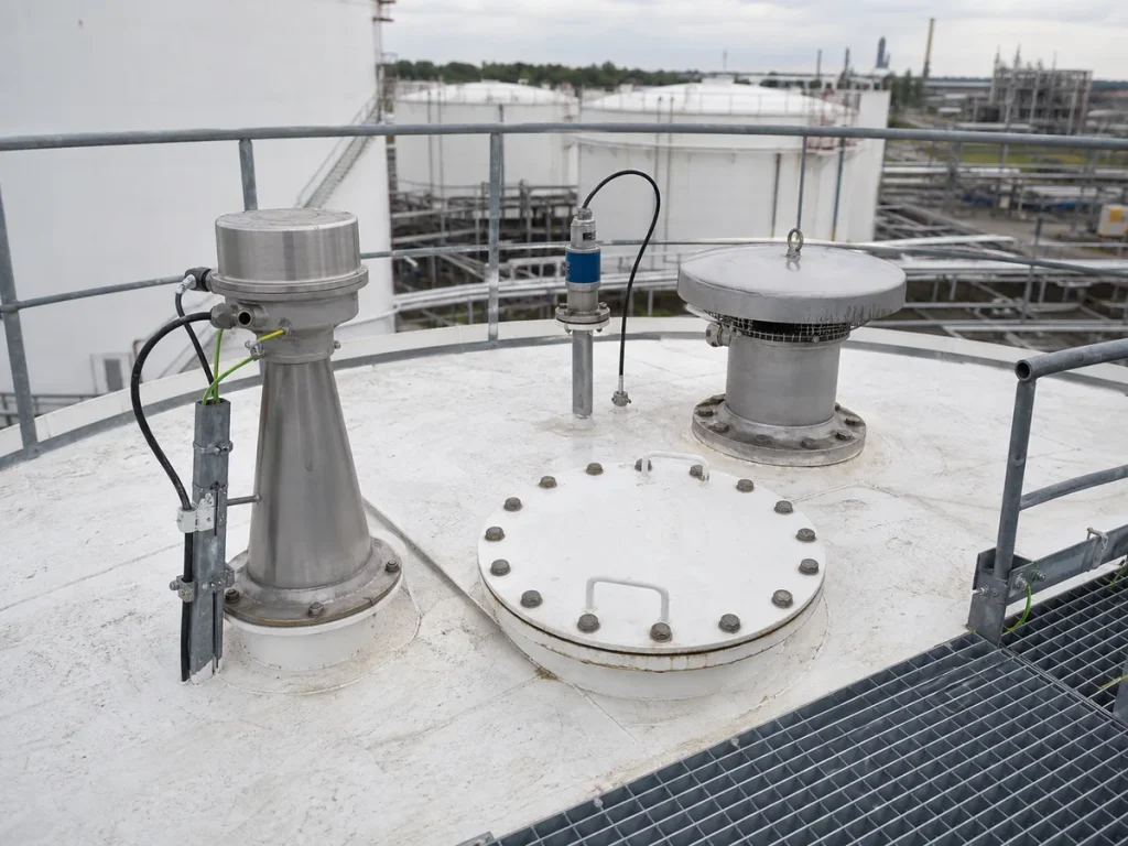
Independent High-High Protection
A serious overfill protection system should not assume that one transmitter, one power supply, one input card, and one unverified configuration will always work. For higher-consequence service, an independent high-high level device can provide a separate protective signal. Depending on the risk assessment, the final action may be an alarm requiring immediate response, an automated inlet isolation, transfer pump shutdown, upstream trip, or a combination.
Independence has practical details. A separate sensing technology may help, but true separation also considers mounting location, power, wiring, input channels, logic solver, maintenance bypasses, common cause failures, and whether both devices can be defeated by the same plugged nozzle, roof damage, or inaccurate reference level. Independence should be demonstrated by design review rather than assumed because two devices happen to be mounted near each other.
Response Time Is an Engineering Calculation
Alarm setpoints must be related to the actual transfer rate and the stopping sequence. Total response time includes alarm detection, signal processing, operator recognition where applicable, communication, pump run-down, valve travel, line packing, and any flow that continues from an upstream elevation or vessel. A large inlet line can keep filling a tank after a pump trip. A remote valve may close slowly. A ship, railcar, road tanker, or pipeline operation may have its own delay before flow is controlled.
EPC documentation should identify the assumed maximum credible flow rate and calculate the volume that can enter during the full response period. This is the basis for the separation between high alarm, high-high trip, and maximum safe level. The calculation should be reviewed when a pump, valve, pipeline, control philosophy, or operating procedure changes.
Final Elements: Pumps, Valves and Transfer Interfaces
An instrument and an alarm do not contain liquid by themselves. The protective action depends on final elements: stopping a pump, closing a motor-operated or actuated valve, isolating a transfer line, stopping an upstream source, or directing an operator to do so. The selected action must actually control the inflow under the facility’s process conditions.
Valve location, fail position, travel time, torque, actuator power, bypasses, manual overrides, position feedback, and maintainability all matter. The tank connection and nearby pipework must also be properly supported. Poorly designed supports or a rigid connection can transfer loads into the nozzle as the line heats, settles, or closes. The tank nozzle, piping, support, and access interface should therefore be part of every overfill protection review.
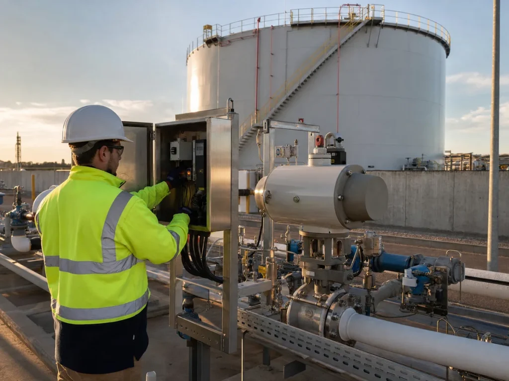
Alarms Need Ownership and a Defined Action
An alarm only provides protection if someone knows what it means and what to do. Each high-level alarm should have a defined priority, operator response, expected response time, escalation path, and rule for resetting or bypassing it. The instruction should name the relevant tank, transfer route, source, isolation point, and communication method. Generic directions such as “check tank level” are weak when several tanks share a manifold.
Alarm rationalization is especially important in control rooms with many nuisance alarms. A high alarm that repeatedly occurs without consequence can be acknowledged out of habit. The remedy is not to make it silent; it is to correct the process, setpoint, configuration, or operating behavior causing nuisance activation, while preserving the alarm’s ability to warn of a real approach to overfill.
Proof Testing and Functional Testing
Inspection of a transmitter display is not the same as proving the complete protective path. A proof test should confirm the selected device senses the simulated level condition, the signal reaches the correct logic, the alarm annunciates where expected, the recorded action is correct, and the final element actually stops or isolates flow as designed. Testing should also include restored normal operation, removal of temporary bypasses, and clear documentation of defects.
Test intervals should be set by the facility’s risk assessment, applicable requirements, device reliability information, service conditions, and management system. The important point is that a test must be realistic enough to find hidden faults. Examples include a stuck float, failed relay, incorrect setpoint, disabled input, reversed valve action, lost air supply, failed actuator, changed logic, or a bypass left in place after maintenance.
Bypass and Override Control
Temporary bypasses are sometimes needed for maintenance or troubleshooting, but they create a period in which the normal protective layer may not exist. Bypass control should identify who authorized it, why it is needed, what compensating measures apply, who knows it is active, when it expires, and how restoration is verified. If a high-high trip is bypassed, the transfer plan may need reduced inventory, a lower transfer rate, continuous attendance, or postponement until protection is restored.
Permanent operational workarounds are a warning sign. Repeatedly overriding a trip, accepting an unreliable gauge, or depending on a single experienced operator can turn a manageable defect into a systemic overfill risk.
Containment and Emergency Readiness
Secondary containment is important, but it is not a substitute for preventing an overfill. A bund may limit the environmental consequence of a release, yet product can still reach drains, equipment, ignition sources, or neighboring areas. Containment capacity, drain valve position, sump condition, rainfall allowance, overflow routes, and emergency isolation should be reviewed alongside the transfer system.
For tank farms handling oils or hazardous liquids, teams should coordinate overfill prevention with the secondary containment, drainage, and leak-risk design. Emergency plans should state how an overfill is recognized, who has authority to stop the source, how the area is isolated, where released liquid could travel, and how communications with upstream or offsite transfer partners work.
EPC Deliverables Before Handover
Overfill protection frequently fails at the interfaces between disciplines. Mechanical design selects roof nozzles; instrumentation supplies a transmitter; electrical powers the panel; automation writes logic; piping supplies the inlet valve; operations develops procedures; and commissioning tests only the parts in its package. The project needs an integrated check that these pieces protect the actual receiving operation.
Before handover, the owner should receive tank calibration information, level instrument data sheets, setpoint register, alarm and trip cause-and-effect matrix, response-time basis, loop drawings, wiring diagrams, valve data, logic narrative, functional test records, bypass procedure, transfer operating procedure, training records, and a schedule for inspection and proof testing. Changes made during commissioning must be reflected in the final documents.
Overfill Prevention Checklist
- Verify the receiving tank identity, current inventory, usable receiving volume, and expected transfer rate before starting.
- Define normal, high, high-high, and maximum safe levels using real tank geometry and response time.
- Select primary level measurement for the liquid, roof configuration, environment, accuracy, and maintenance access.
- Use independent high-high protection where the risk assessment and applicable requirements call for it.
- Calculate the volume entering during alarm recognition, pump run-down, valve travel, line packing, and upstream stop time.
- Verify that pumps, valves, interlocks, and upstream interfaces can actually stop the incoming flow.
- Define alarm ownership, operator actions, escalation, communications, and reset rules.
- Proof-test the complete sensor-to-final-element path and document defects, repairs, bypasses, and restoration.
- Control temporary overrides with authorization, compensating measures, expiry, and independent verification.
- Review containment, drains, emergency isolation, and spill response as consequence controls, not primary prevention.
- Maintain a current setpoint register, cause-and-effect matrix, operating procedure, and commissioning record.
Key Takeaway
Reliable overfill prevention is a managed system, not a single alarm. A tank needs verified capacity, sound level measurement, meaningful setpoints, independent protection where justified, functioning final elements, enough response time, controlled bypasses, trained operators, proof testing, and current documentation. When those elements are coordinated during EPC design and maintained through operations, the facility is far more likely to stop an overfill before it becomes a release.