
Fire protection for an above-ground storage tank is not a single foam chamber, water ring, or alarm panel. It is a coordinated set of prevention, detection, isolation, exposure protection, firefighting capability, containment, drainage, emergency response, and access controls. The correct arrangement depends on the stored material, tank construction, roof type, capacity, operating temperature, vapor behavior, adjacent exposures, site firewater capability, local rules, and the responsible authority’s requirements.
A tank fire scenario is highly site-specific. A fixed-roof tank containing an ignitable liquid, an external floating-roof tank, a water tank, and a protected double-wall package tank do not present the same ignition, vapor, spill, or extinguishment considerations. This article provides engineering planning checks rather than a universal design recipe. System sizing, discharge methods, operating philosophy, and acceptance criteria must be determined by qualified fire-protection and process engineers using the applicable codes, listings or approvals, product data, and site emergency plan.
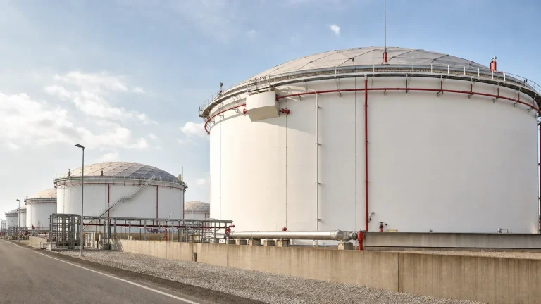
Define the Fire and Exposure Hazards First
Start with a credible hazard review. The project team should understand the product flash point and vapor behavior, storage temperature, transfer operations, possible loss-of-containment paths, ignition sources, tank roof and vent arrangement, nearby tanks and structures, drainage direction, access for responders, and the potential for radiant heat or smoke to affect adjacent equipment. The result should identify what the protection system is expected to accomplish: prevent escalation, protect an exposed tank, control a spill fire, support extinguishment of a tank fire, provide detection and shutdown, or a combination of these objectives.
Tank geometry and arrangement matter. A nearby tank can be an exposure even when it is not the incident tank. Dikes, pipe racks, loading stations, pump areas, and control rooms can change both the fire scenario and the route that personnel or equipment must use. The fire-protection concept should be coordinated with the site’s tank farm layout, spacing, access, drainage, and fire-safety design, rather than added after civil and process decisions are already fixed.
Foam Protection: Match the System to the Hazard
Foam systems are commonly considered where a liquid-surface fire or spill-fire scenario requires a stable foam blanket to suppress vapor release and support extinguishment. Depending on the tank and hazard, the protection concept may use fixed, semi-fixed, mobile, or portable equipment. Fixed-roof tank arrangements can include engineered discharge devices near the roof or other approved application approaches. The feasible method depends on tank construction, product compatibility, foam type, discharge device listing or approval, available water, concentrate supply, and the expected incident management plan.
Foam concentrate is not interchangeable by name alone. The selected concentrate, proportioning equipment, water source, pipework, discharge device, and application method need to be compatible and supported by the applicable listing, approval, manufacturer instructions, and project specification. A change in concentrate chemistry or environmental policy can affect the equipment, hydraulic basis, containment strategy, testing method, procurement lead time, and storage conditions. Treat a foam-system change as an engineered change, not a procurement substitution.
Cooling Water and Exposure Protection
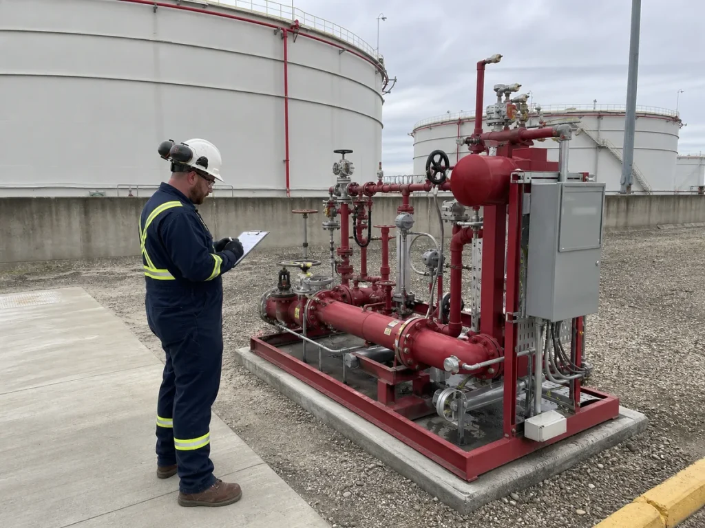
Water spray, monitors, hydrants, or other firewater arrangements may be intended to cool an exposed shell, roof, or adjacent equipment, depending on the approved hazard analysis. Exposure cooling is different from applying foam to a burning liquid surface. Its reliability depends on water supply, hydraulic capacity, valve actuation, distribution, support design, weather protection, and the ability to operate safely during an incident.
The design must account for the full firewater network, not only the piping visible at the tank. Fire pumps, storage, suction conditions, electrical or diesel power, sectional isolation, pressure control, underground mains, remote demand, and test connections all influence whether water arrives where it is needed. Designers should avoid assuming that a general service-water line can perform as a firewater source without a documented hydraulic and reliability review.
Detection, Alarm and Isolation Interfaces
Detection can include flame, heat, gas, smoke, manual call points, tank alarms, or operational indications selected for the actual environment. A detector does not extinguish a fire; it supplies information to people and protection systems. The project needs a clear cause-and-effect narrative showing which alarm reaches which location, which devices may start automatically, which actions require human confirmation, and how faults or impairments are announced.
Isolation logic must be established with process operations. An incident may require stopping transfer pumps, closing selected remote-operated valves, inhibiting automatic sequences, isolating electrical equipment, or preventing additional product from entering the affected area. These functions should be evaluated for process safety and operability. A poorly coordinated automatic action can introduce a separate hazard, so fire-protection, process, electrical, instrumentation, and operations teams need one reviewed response philosophy.
Emergency Venting and Roof Interfaces
Fire exposure can raise pressure inside a tank. Emergency venting is therefore a critical interface between the tank design and the fire-protection strategy. Vents, relief devices, roof seams, flame-control devices where applicable, vapor connections, and weather protection must be selected so that the intended emergency function is not blocked, isolated, plugged, or compromised by an added cover or insulation detail.
The team should coordinate the fire case with the tank’s roof design, normal venting, floating-roof details, rainwater management, and EPC checks. Normal breathing capacity and emergency fire relief are different functions. Neither should be assumed solely from a roof drawing; both need the applicable design basis, product conditions, and standard or authority requirements.
Containment, Drainage and Foam-Water Runoff
Suppression and cooling operations can generate a substantial water-and-foam runoff stream in addition to released product or rainwater. The site must keep that flow from reaching uncontrolled areas, waterways, neighboring property, or equipment that needs to remain operable. Dikes, drains, isolation valves, sumps, impounding arrangements, remote collection, and response procedures must be considered together.
Firewater drainage should be treated as a scenario-based design problem. The required containment and handling approach depends on the incident, the foam concentrate, product contamination, rainfall, available storage, environmental obligations, and response duration. The project should align this work with its secondary containment, drainage, and leak-risk controls, including clear operating ownership for drain positions during normal operation, testing, rainfall, and an emergency.
Access, Manual Operations and Emergency Response
Fire-protection equipment has little value if responders cannot reach it safely. Hydrants, monitors, foam connections, valve stations, control panels, and access roads need suitable location, lighting, identification, and protection from vehicles or routine maintenance work. The layout must also leave room for hoses, apparatus, personnel, and safe retreat routes without forcing responders into a dike or directly beneath a potential exposure.
Manual valves and connections should be positioned with the expected incident conditions in mind. An operator should not need to climb a damaged platform, cross a spill path, enter an exposed area, or search through unmarked piping to initiate the planned response. The emergency plan should define who is authorized to operate each device, what conditions require evacuation or escalation, and when outside emergency services take command.
Commissioning and Integrated Testing
Commissioning should prove the complete functional path: equipment identity, mechanical installation, valve line-up, firewater availability, power, alarm indication, control logic, remote signals, access, drainage configuration, and documentation. A test plan should distinguish between inspection, flow or pressure tests, functional alarm tests, control-logic tests, and any foam-related acceptance activity. Each test needs a safe method, correct containment, competent oversight, and restoration steps so that testing does not leave a system impaired.
As-built drawings should show foam and firewater pipe routes, sectional valves, hydraulic zones, drain paths, detectors, release panels, cable routes, and equipment tags. The handover package should include data sheets, approvals or listings, test records, impairment procedures, maintenance instructions, spare-parts requirements, and training records. Hidden problems often appear later because a valve was buried by a civil change, an enclosure was not weatherproofed, or the control room never received the final signal mapping.
Inspection, Maintenance and Impairment Control
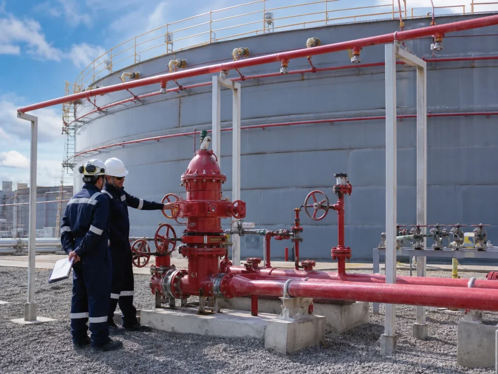
Storage-tank fire protection is a living system. Valves can be shut, strainers can foul, foam concentrate can degrade or be replaced, detectors can be obstructed, water supplies can be impaired, and access can be blocked by later work. Inspection and testing should follow the approved facility program, the equipment manufacturer requirements, applicable standards, and the authority having jurisdiction. Records should identify what was checked, what was unavailable, how impairments were controlled, and when normal protection was restored.
Impairment management deserves special attention. Before a firewater main, foam system, detector, valve, pump, or control panel is removed from service, the owner should understand the affected tanks and exposures, notify the required parties, establish compensating measures, control the duration, and formally verify restoration. A system that appears installed but is isolated or unavailable is not a reliable layer of protection.
EPC Checklist for Above-Ground Tank Fire Protection
- Document the stored product, tank construction, roof and vent details, credible fire and spill scenarios, adjacent exposures, and governing authority requirements.
- Define whether foam, cooling water, detection, manual response equipment, isolation, emergency venting, and containment are required for each tank and exposure scenario.
- Select foam concentrate, proportioning equipment, water source, discharge devices, and pipework as a compatible approved or listed system for the intended hazard.
- Verify the firewater supply, pumps, storage, power, network hydraulics, sectional isolation, and simultaneous demand assumptions through the approved design basis.
- Coordinate alarm cause-and-effect, process isolation, emergency shutdown, electrical interfaces, and operations response before control panels are programmed.
- Preserve emergency venting and safe access while coordinating roof details, platforms, insulation, piping, and weather protection.
- Provide controlled drainage and containment for product, firewater, foam solution, and rainfall under both normal and emergency conditions.
- Commission the mechanical, electrical, control, alarm, water, access, and documentation paths together; record impairments and complete restoration.
Key Takeaway
Reliable storage-tank fire protection comes from a coherent system, not from isolated equipment. A defensible design connects the actual product hazard with foam or water capability, detection, process isolation, emergency venting, containment, access, tested controls, and a trained response organization. Treating these interfaces as EPC deliverables makes the protection arrangement more likely to work when the site needs it.