
An earthquake loads an above-ground storage tank as a coupled system: liquid moves, the shell and bottom respond, the foundation deforms, anchors or unanchored uplift mechanisms engage, and connected piping resists or accommodates relative movement. A tank that looks sound in normal operation can still be vulnerable when one of these interfaces has been omitted from the design basis.
Seismic design is therefore not a generic anchor-bolt detail. The governing requirements depend on site seismicity, soil conditions, tank geometry, stored-liquid density and operating level, roof type, wind and uplift combinations, applicable tank standard, building or seismic code, and the owner’s risk criteria. Qualified structural, geotechnical, tank, piping, and process engineers should establish the design basis for the specific project.
Establish the Seismic Design Basis Before Procurement
The design team needs reliable site inputs: the applicable seismic hazard parameters, site class or soil profile, groundwater condition, liquefaction and settlement potential where relevant, design spectrum, importance or risk category, and the governing code or authority requirements. These inputs affect more than the tank shell. They influence the ringwall, piles or soil improvement where used, anchors, pipe supports, cable routes, dike walls, pumps, and emergency access.
Tank data must be equally clear. Confirm diameter, shell height and course thickness, bottom and annular details, roof and floating components, design liquid density, normal and maximum filling levels, internal equipment, heating coils, mixers, nozzle sizes, existing repairs, and whether the tank is new, modified, or being assessed in service. A seismic assessment based on an assumed product or fill level can miss the critical operating condition.
Liquid Sloshing and Freeboard
During horizontal shaking, part of the liquid responds with the tank while another part moves relative to it. This convective motion can create sloshing at the liquid surface, while impulsive response contributes to shell and base forces. The resulting wave height, freeboard need, roof clearance, floating-roof behavior, and overflow risk should be checked through the applicable design method rather than estimated visually.
Sloshing is not only a product-loss issue. It can affect roof appurtenances, gauges, seals, vents, internal columns, overflow paths, and nearby ignition or spill hazards. The emergency and normal venting arrangement must remain functional under credible movement and not be blocked by a roof detail, maintenance modification, or improvised cover.
Anchored and Unanchored Tank Behavior
Some flat-bottom tanks are designed to remain unanchored under specified conditions; others require anchorage to control uplift, overturning, sliding, or shell stability. Neither condition should be selected by habit. The analysis must consider the code-required load combinations, tank geometry, foundation resistance, shell-to-bottom behavior, liquid level, roof weight, wind, and seismic demand. Adding anchors to an existing tank can shift load paths into shell attachments, bottom details, and concrete that were not originally designed for them.
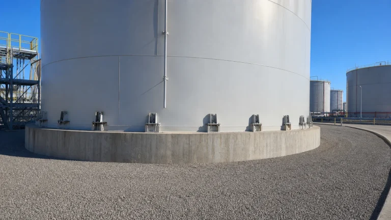
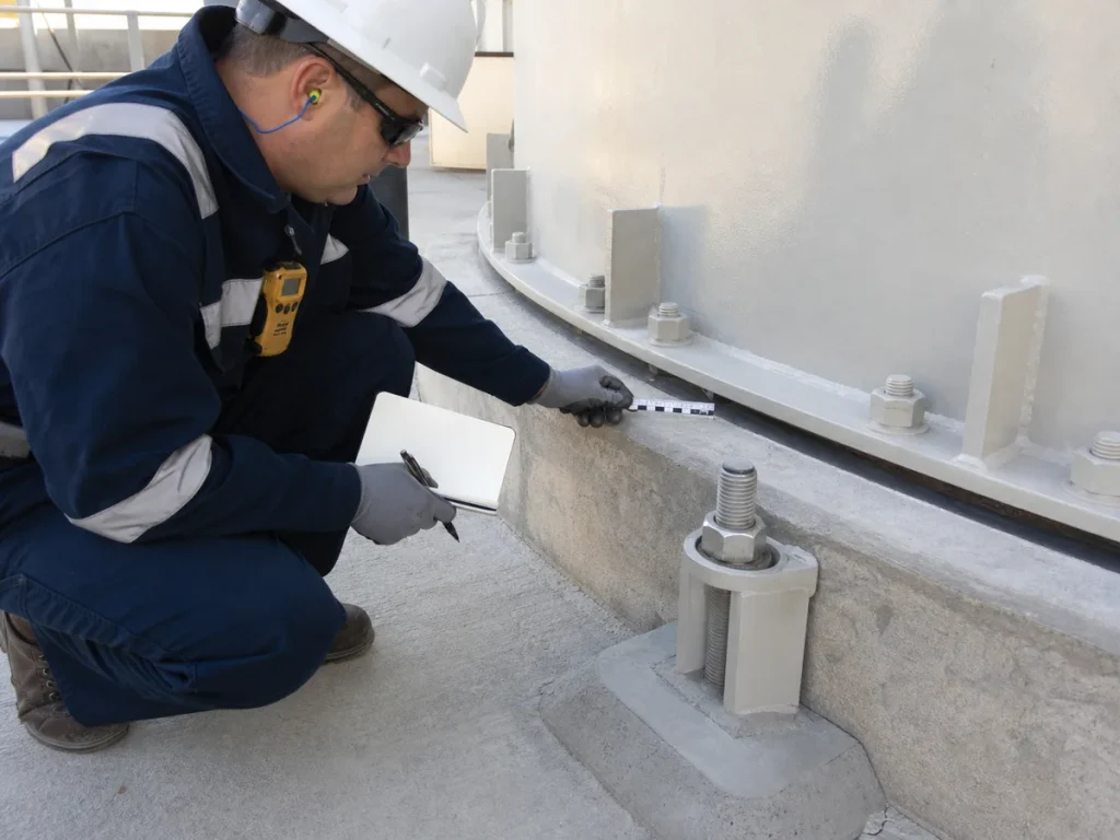
Where anchorage is required, the complete load path matters: shell attachment or anchor chair, welds, bolt, nut and washer arrangement, concrete embedment, reinforcement, edge distance, foundation geometry, grout or shim details, and corrosion protection. Anchor layout must also leave access for inspection and tightening checks without creating water traps or conflicts with stairs, dikes, or pipe supports.
Foundation, Soil and Settlement Interfaces
Tank anchorage cannot compensate for an unsuitable foundation. Differential settlement, loss of bearing support, erosion, liquefaction susceptibility, cracking, displaced fill, or an unrestrained ringwall can change the way a tank responds in an earthquake. The structural and geotechnical designs need one coordinated set of assumptions about loads, deformation, drainage, groundwater, and construction sequence.
The project should build on the established above-ground storage tank foundation design and procurement checks. The seismic review should confirm that anchor forces, sliding resistance, uplift reactions, shell loads, and pipe movements are carried into the actual foundation system, not simply into a generic concrete drawing. As-built surveys, reinforcement records, anchor setting templates, and foundation hold points are particularly valuable for later integrity assessment.
Shell, Bottom and Roof Details
Seismic demand can affect shell compression, buckling susceptibility, bottom and annular stresses, shell-to-bottom connections, roof support systems, platforms, stairways, handrails, and floating-roof components. Details that perform adequately for gravity and wind loads may require additional review when cyclic deformation or uplift occurs. Repairs, shell penetrations, corroded zones, and past settlement must be included in the assessment because they can alter local stiffness or strength.
For existing tanks, compare drawings with the actual field condition. Confirm whether anchor chairs are present, whether they are continuous or localized, whether bolts are accessible, and whether bottom-edge sealing or paving hides relevant details. Photographs, thickness data, settlement records, and prior repair reports allow the engineer to distinguish an original design feature from a later modification.
Do Not Let Connected Piping Restrain the Tank
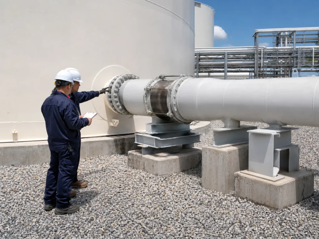
A tank can move relative to adjacent pipe racks, pumps, manifolds, and buried piping. Rigidly connecting the nozzle to a fixed external support can transfer seismic movement into the shell, nozzle neck, flange, pipe support, or valve. Conversely, an uncontrolled pipe can strike equipment or lose containment. The design needs appropriate flexibility, guides, anchors, support gaps, and clearances based on the actual movement envelope and piping stress analysis.
This is why seismic scope must be coordinated with tank nozzles, pipe supports, access, and EPC interface design. Flexible elements are not a cure-all: their pressure rating, travel, fatigue life, fire performance, maintenance access, and installation orientation must be appropriate for the service. A field-installed expansion joint without a reviewed support arrangement can create a new failure mode.
Instrumentation, Electrical and Safety Systems
Level instruments, overfill devices, vents, flame arresters where applicable, mixers, heaters, cathodic-protection leads, grounding conductors, firewater piping, foam connections, lighting, and emergency shutdown wiring all need seismic coordination. Cables need supports and slack or routing that tolerates movement; panels and junction boxes need secure mounting; and sensors must remain accessible after the event. The design should avoid placing critical control equipment where a leaking nozzle, falling platform component, or flooded dike would make it unavailable.
Emergency response planning should consider post-earthquake isolation, product transfer decisions, confined-space restrictions, fire protection impairment, and inspection before a damaged tank is returned to normal operation. A seismic event can create latent damage even when there is no immediate visible release.
Construction, Commissioning and Post-Event Inspection
Construction quality has direct seismic consequences. Verify anchor bolt location and projection before concrete cures, anchor-chair fit-up and weld procedures, foundation elevations, pipe-support settings, nozzle clearances, flexible-connection travel, and drain or dike interfaces. Changes made to resolve a construction clash should be reviewed by the responsible engineer rather than approved as a field convenience.
After a significant event, the inspection plan should address personnel safety first, then visible settlement, shell deformation, damaged anchors, cracked or displaced concrete, pipe and nozzle movement, leaks, roof damage, floating-roof condition, dike damage, electrical hazards, and operability of fire protection. The inspection depth and return-to-service decision should be set by qualified personnel and the site’s emergency procedures. Findings should become part of the tank’s inspection and maintenance program, with photographs, measurements, repairs, and operating restrictions recorded.
EPC Checklist for Seismic Tank Design
- Confirm governing seismic criteria, site class, soil and groundwater conditions, foundation concept, and applicable authority requirements.
- Define tank geometry, liquid properties, operating levels, roof type, internals, wind exposure, and credible load combinations.
- Evaluate sloshing, freeboard, overflow paths, roof clearance, vents, gauges, and floating-roof interfaces through the applicable design method.
- Decide anchored or unanchored behavior from analysis; do not add or omit anchors as a standard detail.
- Design the full anchor load path, including attachments, welds, bolts, concrete, reinforcement, corrosion protection, and future inspection access.
- Coordinate foundation stiffness, settlement tolerance, drainage, anchor reactions, pipe movements, and dike geometry with geotechnical and civil work.
- Provide reviewed pipe flexibility, guides, supports, clearances, and nozzle-load control for credible relative movement.
- Capture as-built anchor, foundation, piping, and equipment information; establish post-event inspection and controlled return-to-service procedures.
Key Takeaway
Seismic resilience is achieved when the tank, liquid, foundation, anchors, piping, safety systems, and inspection plan work together. The strongest individual component cannot compensate for an unreviewed interface. A clear design basis, disciplined construction verification, and documented post-event inspection give an industrial storage tank a practical path to safer performance in seismic regions.