
Oil-water separation is one of the most common industrial wastewater pretreatment steps, but it is also one of the most frequently misunderstood. A separator can remove free oil when oil droplets have enough size, density difference, and calm retention time to rise to the surface. It cannot magically solve every oily wastewater problem, especially when oil is emulsified, chemically dispersed, attached to fine solids, or stabilized by surfactants.
For EPC projects, an oil-water separator should be designed as a process unit with clear feed assumptions, hydraulic limits, skimming equipment, sludge removal, access, sampling, and downstream integration. Treating it as a simple tank purchase often leads to high effluent oil, blocked coalescing plates, odor, sludge accumulation, poor skimming, or overload of downstream DAF and biological systems.
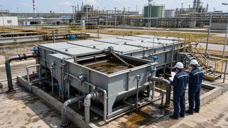
What an Oil-Water Separator Can and Cannot Do
Oil-water separators are primarily intended to remove free and separable oil. In simple terms, oil droplets that are lighter than water can rise if the wastewater is given low turbulence and enough time. Larger droplets rise faster. Smaller droplets rise slowly. Droplets attached to suspended solids, stabilized by detergents, or broken into fine emulsions may not separate well by gravity alone.
This distinction matters during design. If the project wastewater contains mostly free oil from equipment washdown, cooling water leaks, maintenance drainage, tank farm runoff, or oily floor drains, a separator can be effective. If the wastewater contains stable emulsions from high-pressure washing, alkaline cleaners, surfactants, machining fluids, or chemical dispersants, the separator may need upstream source control or downstream chemical treatment.
1. Start With Oil Characterization
The design team should not define the separator only by flow rate. It should review oil concentration, oil type, density, viscosity, temperature, droplet size, suspended solids, detergents, pH, salinity, peak flow, stormwater dilution, batch discharges, and possible future production changes. A separator handling warm food-processing fat behaves differently from one handling mineral oil, refinery runoff, metalworking fluids, or mixed industrial drainage.
Sampling should distinguish total oil and grease from free oil that can separate by gravity. A high total oil and grease number does not automatically mean that a gravity separator will meet the required outlet quality. If jar testing or pilot observation shows that the oil layer does not form clearly, the problem may be emulsion control rather than separator area alone.
2. Control Flow Before the Separator
Gravity separation is sensitive to hydraulic turbulence. Sudden surges, pump cycling, short-circuiting, inlet jetting, and poor distribution can carry oil droplets through the separator before they rise. Equalized and steady feed is usually better than intermittent high-velocity discharge.
Where influent varies strongly, an industrial wastewater equalization tank can protect the separator from hydraulic shock and concentration swings. However, equalization must be designed carefully for oily wastewater. Excessive mixing can break oil droplets into smaller droplets. Long retention time without sludge or oil removal can create odor, floating scum, and cleaning problems.
3. API, CPI and Coalescing Separators
An API-style separator uses gravity, surface area, calm flow, oil skimming, and sludge removal to separate free oil and settleable solids. It is usually a larger rectangular basin or tank with inlet distribution, baffles, oil collection, sludge removal, and an outlet weir. It can be robust, inspectable, and appropriate for high flows where space is available.
CPI separators and other plate coalescers use inclined plates to reduce the distance oil droplets must travel before contacting a surface and coalescing into larger droplets. This can reduce footprint and improve separation of fine but still separable oil droplets. Plate systems, however, are more sensitive to solids, grease, biological growth, debris, and poor cleaning access.
Package coalescing separators can be useful for smaller flows or contained equipment areas, but their success depends on realistic feed assumptions. If the influent brings grit, rags, heavy sludge, or sticky solids, screens, grit removal, or upstream settling may be needed before the plate pack.
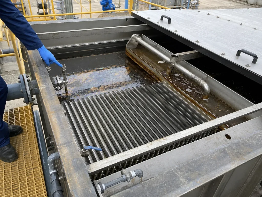
4. Inlet Design Affects Separation
The inlet should slow and distribute flow without creating excessive turbulence. Baffles, stilling zones, perforated distribution pipes, or inlet chambers may be used to spread the flow across the separator width. A high-velocity inlet jet can resuspend sludge, break oil droplets, and push flow directly toward the outlet.
For outdoor or mixed drainage systems, the inlet should also account for debris and grit. If sand, scale, packaging debris, fibers, or sludge enter the separator, they can accumulate in inlet zones, block plate packs, and reduce effective volume. Access for cleaning the inlet section is therefore part of process design, not just maintenance convenience.
5. Skimming Must Match the Oil Layer
Oil removed by the separator must leave the unit reliably. Common arrangements include slotted pipes, rotating skimmers, belt skimmers, tube skimmers, weirs, collection troughs, or manual draw-off points. The right choice depends on oil thickness, viscosity, solids content, operating temperature, maintenance access, and whether the oil layer forms continuously or intermittently.
Skimming equipment should avoid pulling excessive water with the oil. If skimming is too aggressive, oil storage fills with water and disposal cost increases. If skimming is too weak, oil accumulates, re-entrains, creates odor, and may pass downstream during flow changes. Operators should have a practical way to observe oil layer thickness and adjust the system.
6. Sludge and Settled Solids Are Often the Hidden Problem
Oil-water separators frequently receive grit, scale, corrosion products, process solids, biological solids, and oily sludge. If sludge is not removed, it reduces working volume, disrupts flow distribution, contaminates oil removal, and can release odor. Sludge can also cover coalescing plates and block flow paths.
The design should define sludge hoppers, drain points, vacuum truck access, pump-out connections, isolation valves, washdown points, and safe cleaning procedures. If the separator produces significant oily sludge, its handling should connect to the broader industrial wastewater sludge dewatering system strategy rather than being treated as an occasional nuisance.
7. Emulsified Oil Needs a Different Approach
When oil is emulsified, droplets may be too small or too stable to rise in a gravity separator. Emulsions can be created by surfactants, detergents, caustic cleaning, mechanical shear, high-pressure pumps, recirculation, or long pumping distances. In these cases, simply adding more separator volume may not solve the problem.
Possible responses include source segregation, reducing surfactant use, preventing high-shear pumping, adjusting pH, adding demulsifier, using coagulation and flocculation, or sending the stream to a DAF system. If chemical destabilization is required, downstream dissolved air flotation for industrial wastewater may remove oil and suspended solids more effectively than gravity separation alone.
8. Temperature and Viscosity Change Performance
Oil separation can change significantly with temperature. Warmer oil may be less viscous and rise more easily, while cooler fat, grease, or heavy oil may become sticky, slow-moving, or semi-solid. Outdoor separators in cold climates may need covers, insulation, heat tracing, or operational procedures to prevent oil and sludge from becoming difficult to remove.
Temperature can also affect odor, biological growth, worker exposure, material selection, and downstream treatment. EPC teams should not assume that performance observed during one season will automatically represent year-round operation.
9. Outlet Design and Sampling Points
The outlet should minimize carryover of floating oil and settled solids. Adjustable weirs, outlet baffles, submerged outlets, and calm effluent zones can help maintain separation. Poor outlet geometry can draw oil from the surface or pull sludge from the bottom during flow peaks.
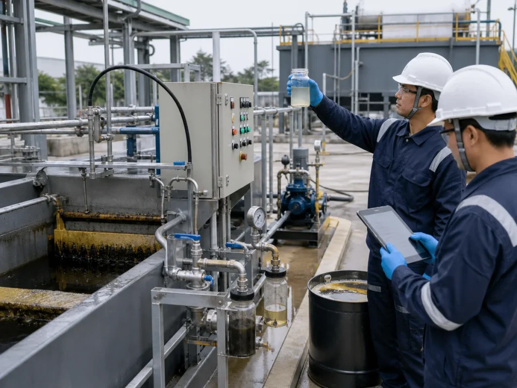
Sampling points should be located where they represent actual treated effluent, not a stagnant corner or a mixed return line. Operators also need practical visual inspection points for influent, separated oil, sludge accumulation, and effluent clarity. Without these points, troubleshooting becomes guesswork.
10. Materials, Coatings and Corrosion
Separator materials should match wastewater chemistry, oil type, cleaning chemicals, temperature, abrasion, outdoor exposure, and expected maintenance method. Carbon steel may need coating or lining. Stainless steel, FRP, coated concrete, or HDPE may be considered in certain services. Internal parts such as plates, skimmers, chains, bearings, and fasteners should be reviewed for corrosion and fouling.
Coatings and linings must tolerate oil, water, cleaning agents, abrasion, UV exposure where applicable, and periodic maintenance. The design should also avoid dead pockets where corrosive sludge or stagnant oily water can accumulate.
11. Integration With Downstream Treatment
The separator is often the first major barrier protecting downstream units. If oil carryover is high, it can foul DAF chemical systems, coat biological tanks, increase sludge volume, reduce membrane performance, create odors, and interfere with instrumentation. Conversely, a well-operated separator can reduce chemical demand and stabilize the rest of the plant.
EPC design should therefore define expected separator outlet quality, alarm response, bypass policy, maintenance isolation, and what happens during storm peaks or abnormal production discharges. A bypass that protects the separator but sends oil downstream may only move the problem to another unit.
12. Commissioning Should Use Real Oily Wastewater
Clean-water testing can confirm leaks, pump rotation, valve operation, and basic controls, but it cannot prove oil separation performance. Commissioning should observe actual oily wastewater under representative flow and temperature conditions. The team should check influent distribution, residence time, oil layer formation, skimmer operation, sludge removal, effluent clarity, sampling consistency, alarms, and downstream impact.
Startup records should capture flow, temperature, inlet oil and grease, outlet oil and grease, visible oil layer, sludge depth, skimmer runtime, oil disposal volume, cleaning frequency, and abnormal events. These records help the owner understand whether the separator is performing as designed or only appearing acceptable during low-load operation.
Oil-Water Separator EPC Checklist
- Confirm whether the oil is free, dispersed, emulsified, attached to solids, or mixed with surfactants and cleaning chemicals.
- Define average flow, peak flow, batch discharge, stormwater impact, temperature range, and future expansion needs.
- Select API, CPI, coalescing plate, or package separator based on oil behavior, solids loading, footprint, and cleaning access.
- Design inlet distribution, calm zones, baffles, outlet weirs, and sampling points to reduce short-circuiting.
- Provide skimming equipment that matches oil layer thickness, viscosity, and operating frequency.
- Plan sludge hoppers, cleanouts, pump-out connections, washdown, isolation, and safe maintenance access.
- Check whether emulsified oil needs pH adjustment, demulsifier, coagulation, DAF, or source control.
- Review materials, coatings, corrosion resistance, and weather protection for the real wastewater service.
- Coordinate separator outlet quality with DAF, biological treatment, membranes, sludge handling, and odor control.
- Commission the unit with real wastewater and record oil removal, sludge behavior, skimmer performance, and effluent quality.
Common Mistakes to Avoid
The most common mistake is assuming that every oil and grease problem is a gravity separation problem. Stable emulsions, fine dispersed oil, and oil attached to solids may need chemical or physical treatment beyond a separator. The second mistake is ignoring solids. A separator that fills with sludge will not provide its designed retention time.
Another frequent mistake is selecting equipment by nominal flow while ignoring peak flow, inlet turbulence, cleaning access, and downstream sensitivity. A compact plate separator can work well when feed is controlled and solids are managed, but it can become a maintenance problem if used as a debris trap.
Conclusion
Industrial wastewater oil-water separators are valuable pretreatment units when their limits are understood. They are strongest at removing free oil under calm hydraulic conditions, with good inlet distribution, skimming, sludge control, and operator access. They are weaker against stable emulsions, high solids, surfactants, and high-shear wastewater.
For EPC projects, the best design starts with wastewater characterization, then coordinates separator type, hydraulic control, plate or basin design, oil removal, sludge handling, materials, sampling, and downstream treatment. That system-level approach is more reliable than treating the separator as a standalone tank.