
Vapor control at an industrial storage tank is an operating, environmental, and mechanical-integrity issue. A fixed-roof tank changes vapor-space volume when it is filled, emptied, heated, cooled, or exposed to daily weather changes. Depending on the stored liquid and tank service, that movement can create routine vapor losses, pressure excursions, vacuum conditions, condensate, odor, flammability concerns, or an emissions-control obligation.
There is no universal vent or vapor-recovery arrangement. The correct design depends on the liquid’s volatility and composition, expected fill and withdrawal rates, vapor pressure, temperature, tank pressure rating, roof and vent details, applicable code and permit conditions, control-device capability, and the facility’s emergency operating philosophy. This guide focuses on fixed-roof above-ground tanks. It does not replace a project-specific venting calculation, relief design, hazardous-area review, or environmental permit analysis.
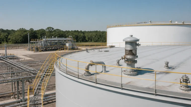
Separate Normal Breathing From Emergency Relief
Normal breathing is the routine air or vapor movement caused by liquid movement and thermal change. A pressure-vacuum vent, conservation vent, closed vent header, or compatible process connection may control this normal duty. Emergency relief is a different function: it addresses abnormal pressure scenarios such as fire exposure or another defined contingency. A vapor-recovery connection must not become a restriction that prevents the tank from using its approved emergency relief path.
Start from a documented basis: tank design pressure and vacuum limits, expected maximum liquid movement, credible thermal scenarios, vent device set points, header backpressure, product behavior, and emergency case. The tank’s roof, fixed or floating configuration, normal venting and rainwater details are essential inputs, not late-stage mechanical details.
Where Fixed-Roof Tank Vapors Come From
Routine fixed-roof emissions are often described as standing or breathing loss and working loss. Standing loss relates to vapor-space changes during storage, while working loss accompanies filling and vapor displacement. The magnitude depends on product volatility, turnover, temperature, vapor-space volume, roof condition, and local atmospheric conditions. Product received from a pressurized source can add a flashing or entrained-gas component that needs separate process review.
Emission estimation and control selection should use the applicable local methodology and actual product data. A tank holding a low-volatility liquid may need a very different solution from a tank holding crude, condensate, gasoline-range material, or a chemical with hazardous vapor characteristics.
Pressure-Vacuum Vents and Closed Vent Headers
A P/V vent protects the tank during normal pressure and vacuum movement within its designed range. Its set points, capacity, pallet condition, weather hood, flame-control provisions where required, drain arrangement, and access must align with the tank and service. Fouling, icing, corrosion, incorrect pallets, blocked screens, paint overspray, or an isolated vent can defeat a device that appears installed.
A closed vent system routes normal vapors to recovery or control rather than directly releasing them. It needs enough capacity for the expected flow and a pressure profile compatible with the tank. Header slope, low points, condensate collection, liquid carryover, vacuum risk, isolation valves, thermal expansion, and maintenance bypasses must be engineered as a system. A valve closed for maintenance can inadvertently isolate multiple tanks or produce unacceptable pressure during transfer.

Vapor Recovery Unit Interfaces
Vapor recovery units may compress or otherwise recover low-pressure vapors for reuse, fuel, processing, or another approved destination. They commonly require a liquid knockout arrangement upstream to protect equipment from condensate or liquid carryover. The actual package must be selected for the gas composition, expected vapor rate, pressure range, liquid handling, hazardous area, start-stop behavior, and destination pressure.
Do not assume a VRU has unlimited suction capacity. Simultaneous filling, changing product temperature, multiple connected tanks, or a plugged knockout system can create flows outside the operating envelope. The tank header, separator, compressor, pressure controls, recycle or bypass logic, alarms, and downstream system should be reviewed together through normal, transient, maintenance, and loss-of-power cases.
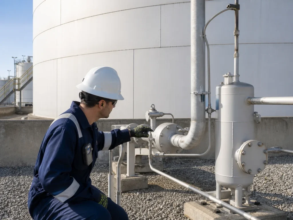
Control, Alarms and Overfill Interfaces
Tank pressure, header pressure, VRU status, liquid level in knockout equipment, valve position, and high-level tank alarms can provide critical operating context. However, the inventory signal and the independent overfill-prevention system have their own safety purpose. A vapor-control project should not alter alarm set points, shutdown action, or the credible transfer response without approved process and safety review.
Cause-and-effect documentation should show what happens if the VRU stops, the header pressure rises, a low-pressure trip occurs, a condensate pot reaches high level, or a tank vent alarms. Operators need clear limits and actions before the system is placed in service.
Commissioning and Maintenance
Commissioning verifies more than pipe continuity. Confirm device identification, set-point basis, directional flow, isolation positions, header routing, electrical classification, grounding where applicable, drains, access, alarms, startup logic, and as-built drawings. Functional testing should use a controlled procedure that does not leave a tank unprotected or release vapors unintentionally.
Inspection should include vent condition, obstruction, corrosion, weather intrusion, unexpected liquid, piping supports, valve lineup, detector and alarm health, and maintenance records. Vapor control also needs coordination with the tank-cleaning and turnaround plan: degassing, cleaning, or opening a tank can produce a vapor condition outside normal operating assumptions.
EPC Checklist
- Define liquid properties, credible flow and thermal cases, tank pressure limits, emergency scenarios, and permit obligations.
- Keep normal pressure management and emergency relief functions independently clear and available.
- Size and route headers for expected pressure, condensate, liquid carryover, isolation, and transient operation.
- Match the recovery package to vapor composition, flow, pressure, hazardous area, liquid handling, and destination.
- Coordinate P/V vents, closed vent systems, VRU controls, tank alarms, overfill protection, and operating procedures.
- Capture commissioning tests, set-point basis, as-builts, maintenance requirements, and impairment controls.
Key Takeaway
Good vapor control protects the tank first, then manages routine emissions through a recoverable and maintainable system. The durable design is one where venting, emergency relief, condensate control, recovery equipment, alarms, and operating response are engineered together rather than assembled as separate packages.