
An above-ground storage tank can lose product through the bottom long before a release is obvious at the shell. The floor is hidden by product during service, may sit on a foundation that limits direct observation, and can be affected by water, soil-side corrosion, settlement, coating condition, product service, and construction details. A bottom leak-detection arrangement is therefore an important early-warning layer for some tanks and sites.
It is not, however, a substitute for tank-bottom integrity, corrosion control, inspection, drainage, or secondary containment. A detector can show that liquid has reached a monitored space or point. It does not prove the condition of every bottom plate, identify every small seepage path, or replace the engineering controls that prevent a release from becoming an environmental event. The design has to fit the tank service, stored product, foundation, local requirements, environmental sensitivity, and owner operating practice.
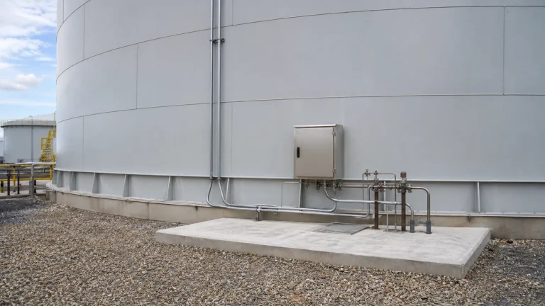
Start With the Detection Objective
The first question is what the system is expected to detect and how quickly it needs to provide useful information. Some projects need a means to indicate liquid in an interstitial space between two bottoms. Others use an under-bottom barrier and a routed collection point, a sump, or a test pipe. A site with sensitive groundwater may also include observation wells as part of a broader environmental monitoring program. Inventory reconciliation and level trends can provide a separate operating indication, but they are not equivalent to a physical bottom-release detection path.
The intended response must be defined at the same time. An alarm might require a trained operator to inspect a test point, verify product movement and level data, stop or reduce a transfer under the approved operating procedure, secure the affected area, and escalate for environmental and integrity assessment. Without a clear response owner, accessible equipment, and records, an installed sensor is only hardware.
Double Bottoms and Interstitial Monitoring
A double-bottom arrangement provides a space or engineered layer between a primary floor and a secondary floor or barrier. The monitored space may be designed to collect leaked liquid at a low point, route it to a test connection, or accommodate a compatible detection method. Its practical value depends on details that can be overlooked during construction: continuity of the layer, weld and penetration treatment, support arrangement, drainage or collection geometry, access, product compatibility, and the ability to test the monitoring route after the tank is in service.
The system should not trap rainwater, construction debris, or process water in a way that creates false indications or blocks the intended collection path. The team needs to establish whether a detected liquid could reasonably be identified, sampled, or traced to a specific zone. For some services, a liquid sensor in a collection point may be suitable. For others, a dry interstitial space, a testable pipe, or a different compatible arrangement is more appropriate. The chosen method should be documented in the tank data package rather than left to an informal site assumption.
Under-Bottom Barriers, Collection Paths and Test Points
Where a project uses an under-bottom impermeable layer, collection channel, or monitoring pipe, the tank foundation and drainage design become part of the detection system. The goal is to guide a release toward an observable location while preventing uncontrolled migration beneath the tank. That requires compatible barrier material, protected joints, a defined fall or collection geometry where used, and a route that remains open after settlement, paving, pipe work, and routine maintenance.
Test points should be clearly identified on drawings and remain reachable without lifting covers, cutting paving, or entering a restricted area. They need physical protection from vehicle impact, weather, unauthorized manipulation, and standing water. The EPC scope should make ownership explicit: civil works may build the foundation, the tank contractor may install bottom components, piping teams may route test connections, and electrical or instrumentation teams may wire alarms. Missing coordination at these interfaces is a frequent source of a monitoring system that cannot be verified at handover.
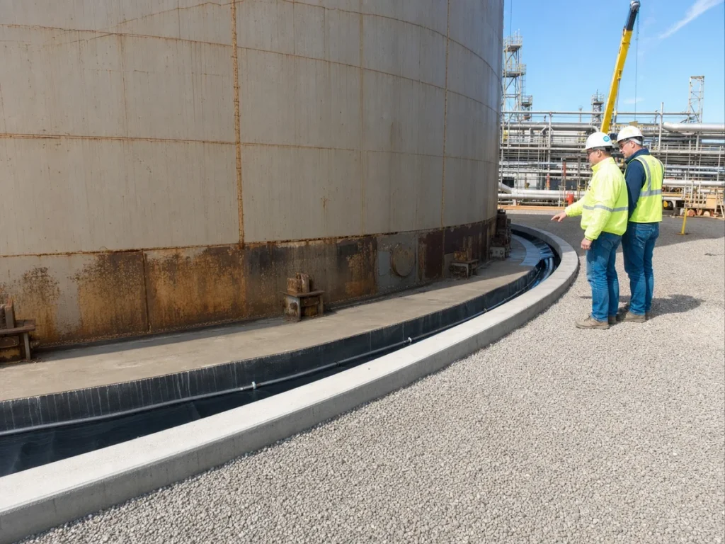
Monitoring Wells Are Site-Specific, Not a Universal Tank Detail
Observation wells, soil-gas points, or groundwater monitoring wells can be valuable at environmentally sensitive facilities, but their design is driven by site hydrogeology and the approved environmental program. Well depth, screen interval, location, sampling method, access, background conditions, and interpretation require qualified input. A well that is poorly located relative to groundwater flow or an impermeable foundation layer may provide little useful evidence about a tank-bottom release.
External monitoring wells should therefore be treated as a complementary environmental control, not as the only means of detecting a leak from an above-ground tank. They can help investigate trends or confirm whether a release has migrated beyond a local detection layer, but they may not provide an immediate or uniquely attributable indication. The owner should coordinate the well program with site environmental obligations and maintain a clear baseline and sampling record.
Instrumented Sensors and Alarm Design
An automated system may use a sensor at a low-point collection location, an interstitial detector, a pressure or vacuum method where the design supports it, or a monitored switch connected to the site control system. Selection should consider the stored product, expected liquid behavior, temperature range, contamination potential, electrical classification, power availability, cable protection, signal reliability, accessibility, and the consequence of a failed or nuisance alarm. A detector that is compatible with water may not be the correct choice for every hydrocarbon or chemical service.
Alarm philosophy matters as much as the sensor. The display or control room signal should distinguish a fault, loss of power or communication, and an actual high-priority detection condition where the system permits. Personnel need a documented method to test the signal path without defeating protection permanently. The test should confirm indication at the local device and any required remote location, and it should leave the system in its normal operating state.
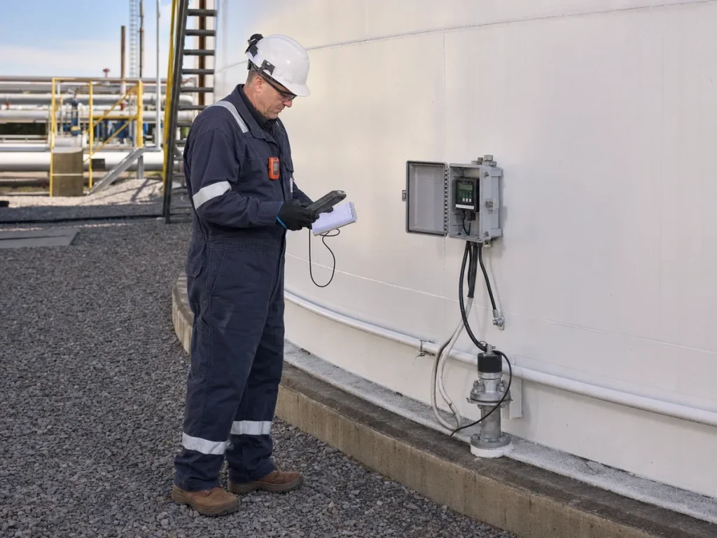
Coordinate Detection With Corrosion Protection and Bottom Integrity
Leak detection does not slow corrosion or repair a thinning floor. The tank owner still needs a disciplined integrity program covering inspection history, floor condition, settlement, water management, coatings or linings where applicable, repair decisions, and corrosion controls. For tanks using a bottom cathodic protection system, the leak-detection layer, anodes, cables, test leads, and foundation details must be coordinated so one system does not damage, isolate, or make the other untestable.
Construction records should identify below-floor materials, cable and pipe routes, isolation details, test points, and penetration locations. This record becomes essential when the tank is repaired years later. A retrofit crew must be able to distinguish a monitored pipe from a drain, a cable from a test lead, and a designed access point from an abandoned installation.
Keep Containment and Drainage Working
A tank-bottom monitoring arrangement provides early information; secondary containment provides a separate layer to control a release at the facility. Bunds, dikes, drainage paths, drain valves, sumps, and surface grading should be reviewed together with the detection plan. A false alarm caused by rainwater entering an unprotected test point is poor design. So is a real release that bypasses a collection path because paving, settlement, or an open penetration directs liquid elsewhere.
The project should connect the design to the facility’s secondary containment, drainage, and leak-risk controls. This includes confirming that emergency drainage decisions, rainwater management, access for response equipment, and containment inspection are addressed in the operating procedure. Detection and containment have different functions, and both need to remain serviceable.
Commissioning: Prove the Whole Detection Path
Commissioning should verify more than the presence of an enclosure. Before handover, the team should inspect the accessible monitoring point, confirm the as-built route, verify equipment identification, check physical protection and weather sealing, and confirm that collection paths or interstitial spaces are not blocked by debris. Where the approved design allows, a controlled functional test or alarm simulation can demonstrate that the local device, cable or wireless link, remote indication, and response record work as intended.
The commissioning package should include drawings, test results, equipment data, product-compatibility information, alarm set-point basis where applicable, photographs of concealed work before cover-up, and a maintenance instruction. Any departures from the original design need formal review. A late change such as relocating a test pipe or burying a collection route may remove the very accessibility the system needs to perform its function.
Inspection, Testing and Alarm Response
Operating personnel should include the detector in routine rounds and the planned maintenance program. Useful checks may include the condition of access covers, standing water, damage to enclosures or conduit, signs of settlement, test-point identification, detector status, and whether prior alarms were investigated and closed. Functional testing frequency and method should follow the approved tank design, equipment manufacturer instructions, applicable requirements, and the facility’s risk-based program rather than an arbitrary interval.
A suspected detection event should be handled through the site’s approved emergency and operating procedures. The initial response commonly focuses on personnel safety, preventing escalation, verifying whether the signal is genuine, reviewing transfers and tank data, protecting containment, documenting conditions, and engaging the appropriate integrity and environmental resources. Findings should update the tank’s inspection and maintenance program, including any repair scope, monitoring trend, or revised control needed before normal operation continues.
EPC Checklist for Tank-Bottom Leak Detection
- Define whether the objective is interstitial detection, collection-point monitoring, environmental monitoring, inventory discrepancy support, or a combination of these controls.
- Confirm product compatibility, temperature, electrical classification, expected liquid behavior, foundation condition, and environmental sensitivity before choosing the method.
- Show barriers, double bottoms, collection routes, monitoring pipes, low points, wells, sensors, cables, and access points on coordinated civil, tank, piping, and electrical drawings.
- Protect monitoring access from rainwater, debris, corrosion, vehicle impact, unauthorized use, and future paving or construction changes.
- Coordinate cathodic protection, grounding, floor repairs, coating or lining work, foundation sealing, and drain details so interfaces remain testable.
- Set the local and remote alarm response, fault indication, functional-test method, documentation, and named owner before handover.
- Capture concealed-work photographs and accurate as-built records before floor layers, concrete, or pavement hide the monitoring path.
- Maintain the device and associated tank integrity controls through a documented inspection and maintenance program.
Key Takeaway
Effective tank-bottom leak detection is an engineered system, not a single sensor. Double bottoms, under-bottom collection layers, test points, monitoring wells, and alarms each have a role when selected for the actual tank and site. The most reliable projects preserve access, coordinate foundations and corrosion controls, prove the alarm path at commissioning, and connect every indication to a defined operating and environmental response.