
Grounding, bonding and lightning protection at an above-ground storage tank are often treated as a small electrical detail added after tank erection. In practice, they are interfaces between the tank shell, roof, floating components, connected piping, product transfer operations, instruments, fire protection, foundation and the site earthing system. A continuity path that is inaccessible, corroded, painted over, removed during repair or disconnected by a modification may not perform as the design intended.
The correct arrangement depends on the tank type, stored product, roof configuration, transfer operations, local lightning exposure, electrical-area classification, applicable standards, site earthing system and owner risk criteria. Bonding and grounding help manage electrical potential differences and static-related ignition hazards; they are not a guarantee against every lightning strike or a substitute for a complete lightning-protection design and operating controls.
Separate Earthing, Bonding and Lightning Protection Functions
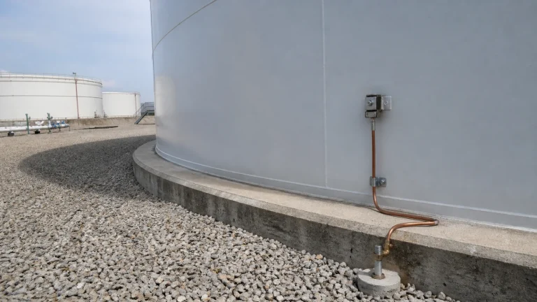
Earthing connects conductive equipment to the site earthing system. Bonding joins conductive parts so that a dangerous voltage difference is less likely to develop between them. Lightning protection evaluates how a direct or nearby strike, induced current, or surge may affect the tank, roof, piping and connected equipment. These functions overlap, but they are not interchangeable. A grounding cable at the shell does not by itself prove a floating roof, gauge hatch, piping connection and electrical enclosure are bonded correctly.
Begin with an electrical and process basis that identifies tank type, roof type, product flammability, vapor conditions, transfer rates, piping and roof appurtenances, nearby structures, earth-grid layout and the governing code. Coordinate it with the tank’s roof, floating-roof and venting configuration, since moving or isolated roof components need different attention from a welded fixed roof.
Tank Shell and Foundation Interfaces
For a steel tank, the shell, grounding lug, test link, conductor, connection hardware, earthing electrode or grid, and foundation penetration need a clearly documented path. Design must consider corrosion, mechanical damage, inadvertent disconnection, concrete work, paving, drainage and access. A buried conductor may be electrically sound but impossible to inspect after a civil modification unless a protected test point and accurate as-built record are retained.
Connections should be made with compatible materials and approved attachment methods. Field changes such as a new coating, shell repair, cathodic-protection lead, pipe support or dike wall can create an electrical interface that needs review. Do not drill, weld, cut or remove a bonding point as a maintenance convenience without the responsible engineering assessment.
Floating Roof Continuity and Rim Components
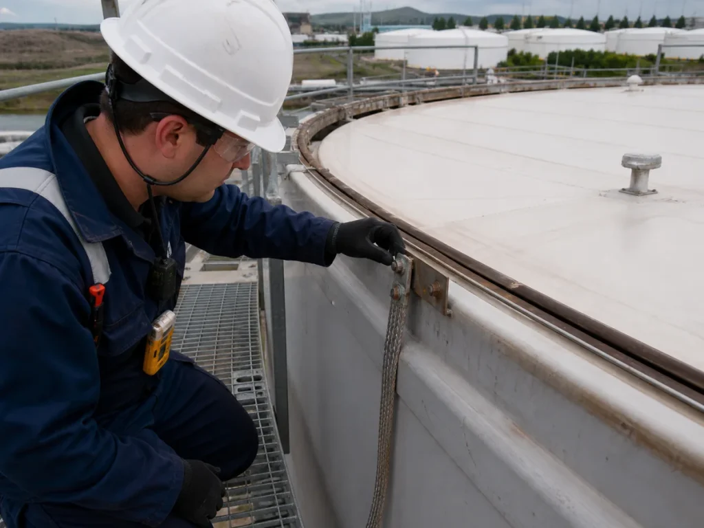
An external floating roof moves with product level while the shell remains stationary. Bonding shunts, cables or other approved continuity components are therefore part of the roof system, along with seals, rim vents, rolling ladders, roof legs and appurtenances. They must have adequate contact, flexibility, current-carrying capability, corrosion resistance and clear travel throughout the roof operating range.
Inspection should look for broken or missing shunts, fouling, loss of contact, corrosion, loose fasteners, damaged braid, painted contact surfaces, excessive roof movement and changes near seals or rim fittings. The design must avoid components snagging on the shell, seal, guide pole or roof accessories. When the tank has a floating roof, the grounding scope cannot be separated from its mechanical integrity.
Static-Control Interfaces During Operations
Static hazards are affected by product properties, transfer method, loading rate, filters, sampling, water or solids, splash filling, hose connections, floating objects and gas or vapor conditions. Grounding and bonding must be accompanied by appropriate operating procedures. A conductor cannot correct an unsafe transfer sequence, an unbonded temporary hose, or an unauthorized opening of equipment in a hazardous atmosphere.
Review permanent and temporary conductive paths at tank inlets, outlets, loading points, sample locations, temporary pumps, vacuum equipment and maintenance connections. Electrical-area classification, equipment suitability and work permits remain separate but connected controls. The facility’s tank fire-protection system also needs to remain available during electrical work; an impairment should be controlled through the approved process.
Inspection, Testing and Records
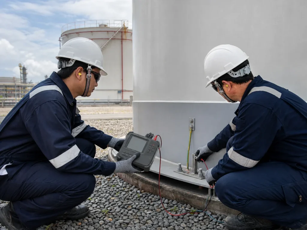
Visual inspection is necessary but not enough. An approved maintenance program should establish how grounding connections, bonds, floating-roof continuity components, test links, conductors, connections and accessible earth points are inspected and electrically tested. The selected method, acceptance basis and frequency depend on the design, applicable requirements, corrosion environment and owner program. Avoid relying on arbitrary readings without knowing the test configuration, soil conditions and design basis.
Results should be traceable to the specific tank and test location. Record physical condition, continuity or resistance result where applicable, instrument identification, date, person performing the work, weather or soil condition if relevant, defects, corrective action and return-to-service confirmation. These records belong with the tank inspection and maintenance program, not only in a general electrical file.
EPC and Modification Checks
- Define tank, roof, product, lightning exposure, static-control, electrical-area and site-earthing requirements before selecting details.
- Show every shell connection, test point, conductor route, grid connection, floating-roof bond and interface with piping or instrumentation on coordinated drawings.
- Protect conductors and lugs from corrosion, coating damage, vehicles, drainage, civil cover-up and unauthorized removal.
- Verify that moving roof components remain electrically continuous across the full operating range without damaging seals or appurtenances.
- Coordinate temporary work, fire-protection impairment, hazardous-area controls, permits and restoration during installation or testing.
- Deliver as-builts, test results, maintenance instructions, accessible test points and change-control requirements to operations.
Key Takeaway
Reliable tank grounding is a maintained system of electrical continuity, not a single cable at the shell. A defensible design identifies all conductive interfaces, keeps bonds accessible, accounts for moving floating-roof components, verifies the path in service and connects the electrical scope to process, mechanical-integrity and fire-protection management.