
Above-ground storage tank bottoms can corrode from the product side and from the soil side. Product-side damage may be linked to water bottoms, sludge, microbes, chemicals, or a failed lining. Soil-side damage develops below the steel floor, where moisture, oxygen, salts, variable pad conditions, poor drainage, and trapped water can create an electrolyte that is difficult to inspect while the tank remains in service.
Cathodic protection, usually called CP, is one engineering tool for reducing soil-side corrosion of steel tank bottoms. It works by supplying protective current so the tank bottom behaves as the cathode in an electrochemical system. But CP is not a substitute for bottom inspection, a sound foundation, internal lining, water management, or a repair decision when the steel is already too thin. The strongest tank-integrity program uses these measures together.
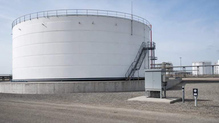
Where Tank Bottom Corrosion Begins
The lower shell and bottom plates sit over a foundation system rather than open air. Depending on the design, that system may include compacted sand, crushed stone, concrete ringwalls, asphaltic materials, liners, a leak-detection layer, or drainage provisions. Water can enter from rainfall at a damaged bottom-edge seal, from poor site drainage, from an ineffective ringwall interface, or through foundation materials. If the environment beneath the floor is conductive and contains oxygen, local corrosion cells can develop.
Conditions are rarely uniform beneath a large tank. Some areas may remain dry and resistive while others retain water or soluble salts. Settlement, floor flexing, inadequate slope, leaking firewater lines, and repairs that alter the pad can change the environment over time. This is why a corrosion engineer should develop the CP basis from the actual tank, foundation, soil, service, and inspection history rather than applying a generic anode quantity.
What Cathodic Protection Can and Cannot Do
CP aims to reduce external electrochemical corrosion on the protected steel surface. API RP 651 is a key industry reference for cathodic protection of above-ground petroleum storage tanks and recognizes that detailed design depends on the installation conditions. The same principles may inform other services, but owners must confirm the applicable regulations, product hazards, design standard, and corrosion-control strategy for their own facility.
CP does not repair existing holes, restore lost thickness, correct major settlement, remove contaminated water under the tank, or prove that an internal lining is compatible with the stored liquid. It also does not eliminate the need for formal floor inspection. A tank with serious bottom deterioration may need internal examination, floor scanning, repairs, a new bottom, or replacement regardless of CP status.
Two Main System Approaches
Galvanic, or sacrificial-anode, systems use anodes made from a metal that is more electrically active than the steel tank. The anodes gradually consume themselves while supplying protective current. They can be attractive for smaller current demands or where the foundation design and electrical environment support their use. Their practical limits include anode life, current output, soil or pad resistivity, access for replacement, and the challenge of distributing current across a large floor.
Impressed-current systems use a DC power source, usually a transformer-rectifier or other controlled supply, to drive current through anodes placed in a designed groundbed or tank-bottom arrangement. They can provide more adjustable current and may suit larger tanks or demanding environments. They also introduce operating duties: power availability, rectifier monitoring, cable integrity, control settings, stray-current interaction, grounding coordination, anode condition, and periodic specialist testing.
Neither option is automatically better. Selection should consider tank diameter, accessible space, expected current demand, foundation construction, electrical resistivity, coating or liner condition, design life, nearby buried structures, power reliability, access for testing and replacement, capital cost, and lifecycle maintenance.
Foundation Design Is Part of the CP Design
A CP system is installed around or below a tank bottom, so the tank foundation cannot be treated as a separate civil detail. The conductive path between anodes and steel depends on the material below the floor, its moisture condition, resistivity, thickness, and continuity. A change from dry compacted sand to wet contaminated sand can affect current distribution. A new ringwall seal, drainage repair, or tank-bottom replacement may change the CP environment again.
The project team should coordinate the CP design with the above-ground storage tank foundation design. Civil, mechanical, corrosion, electrical, instrumentation, and inspection disciplines should agree on anode locations, cable routes, test stations, reference electrode access, ringwall penetrations, isolation requirements, and future maintenance access before concrete and foundation layers make changes expensive.
Electrical Continuity and Isolation
CP current only protects steel that is electrically connected in the intended circuit. The tank bottom, shell, appurtenances, grounding system, piping, and nearby structures must be reviewed so the system performs as designed without creating unintended current paths. Electrical continuity testing may be needed to confirm the tank structure is connected where expected. Conversely, isolation may be needed at particular interfaces to reduce interference or preserve current for the intended tank.
Lightning protection, personnel safety grounding, electrical classification, weld continuity, bonding, and cathodic protection are related but not identical design subjects. They should be coordinated by qualified specialists. A casual field bond or an undocumented cable connection can change CP performance and may complicate safety systems.
Test Stations and Reference Electrodes
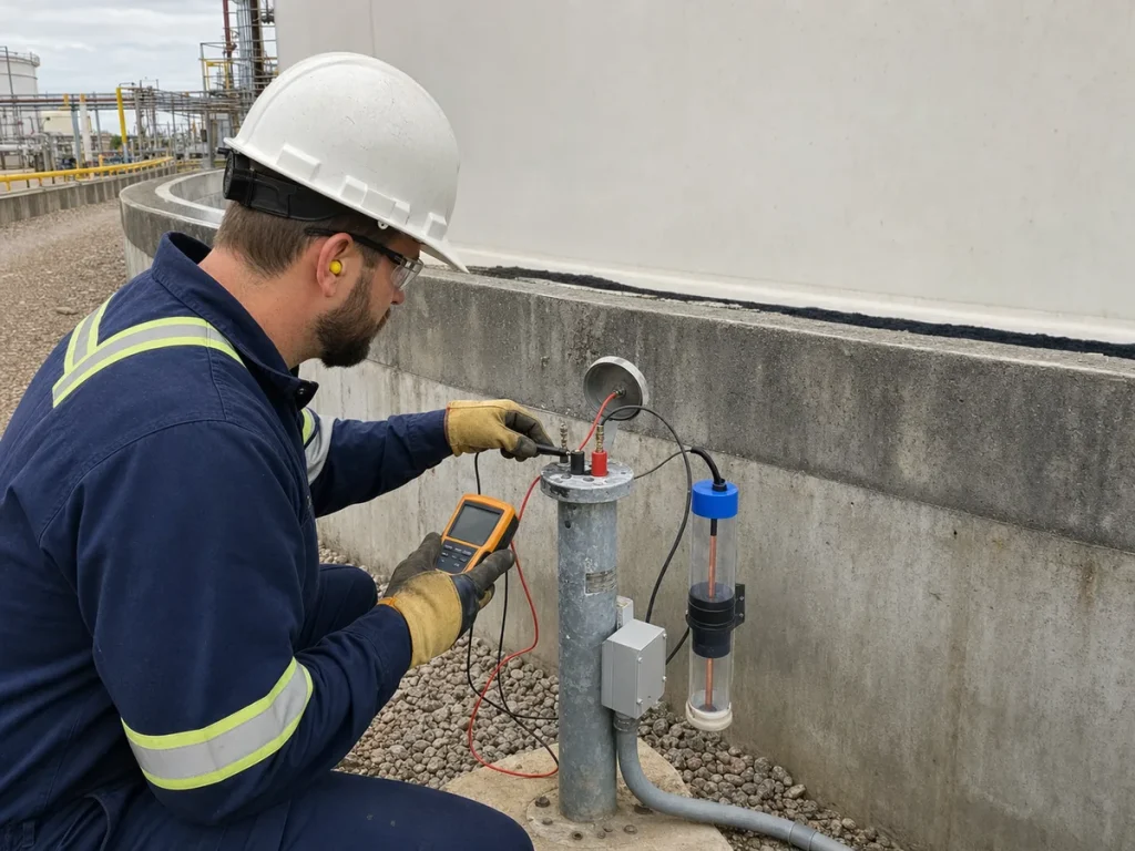
A CP system cannot be managed only from an installation drawing. It needs accessible test points and a measurement plan. Test stations allow technicians to read structure-to-electrolyte potentials, cable continuity, current output, anode circuits, and rectifier operating values. Permanent reference electrodes may be installed where suitable; portable reference electrodes and specialized survey methods may also be used depending on the design and access.
Measurements must be interpreted in context. Readings can be affected by reference electrode placement, IR drop, soil or pad moisture, tank operating condition, nearby current sources, cable faults, temporary connections, and survey method. A value by itself is not proof that every area under a large floor is protected. A competent corrosion specialist should define criteria, locations, method, data quality checks, and follow-up actions.
Commissioning: Prove the Installed System
Commissioning should verify more than an energized rectifier. The handover package should identify the design basis, system type, anode layout, cable routing, test station schedule, isolation locations, design current, expected operating range, commissioning measurements, and acceptance criteria. It should confirm that each circuit is connected as shown, polarity is correct, protective devices are in place, test stations are labeled, and power or solar supply is operating normally.
For impressed-current systems, baseline rectifier voltage and current values should be recorded, but owners should not assume the same settings will remain correct forever. Foundation moisture, seasonal change, anode aging, interference, and repairs can change performance. The system needs an operating envelope and a process for escalation when readings leave it.
Operating and Monitoring the System
Monitoring frequency should follow the applicable standard, local rules, risk assessment, system type, corrosion engineer recommendations, and company integrity program. The exact inspection intervals for underground storage tanks should not be assumed to govern an above-ground tank bottom; these are different applications. What matters is a written plan that defines routine checks, specialist surveys, record retention, abnormal-condition response, and reevaluation after modifications.
For an impressed-current system, operators may record rectifier status, output voltage, output current, power alarms, and physical condition. A change can indicate a tripped breaker, power loss, cable damage, anode issue, altered environment, or a poor connection, but it needs investigation rather than a casual adjustment of the control knob. For galvanic systems, the monitoring plan should account for anode depletion and the fact that an apparently simple passive system still needs periodic confirmation of performance.
Integrate CP With Bottom Inspection
Tank integrity decisions need both electrical and physical evidence. External CP surveys provide information about the corrosion-control system. Internal inspection can reveal product-side corrosion, water-bottom damage, sludge effects, lining breakdown, weld condition, pitting, and actual plate thickness. Floor scanning, ultrasonic mapping, settlement surveys, leak history, and repairs tell a different part of the story.
The CP file should therefore sit alongside the tank’s inspection and maintenance records, not in a separate electrical folder that nobody consults during an outage. When bottom thinning, water ingress, or foundation damage is found, the inspection and corrosion teams should review whether CP current distribution, drainage, foundation materials, edge sealing, or test station results point to a contributing cause.
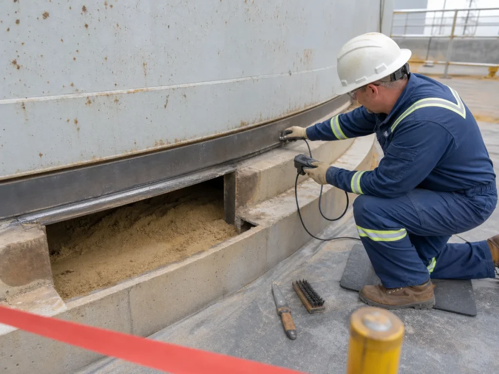
Bottom-Edge Seals, Drainage and Water Control
Rainwater and other liquids near the chime or ringwall deserve attention. An edge seal may help limit the entry of water and debris below the tank, but it must be compatible with movement and maintained rather than treated as permanent once installed. A cracked seal, ponded water, damaged concrete, open penetration, or poorly graded surrounding pavement can undermine a corrosion-control strategy.
Drainage work should not be performed without considering its effect on CP. Removing or adding materials near the ringwall can affect cable routes and electrical conditions. Conversely, CP should not be used as a reason to ignore standing water, washdown discharge, leaking piping, or foundation erosion. The goal is to make the underside environment less corrosive and to maintain the protection system that remains necessary.
Internal Linings Still Have a Different Job
CP primarily addresses the external, soil-side surface of the tank bottom. An internal lining is selected to resist the stored liquid and product-side corrosion mechanisms. The two measures can complement each other, but they are not interchangeable. A lining can fail from poor surface preparation, incompatible service, mechanical impact, thermal cycling, or a damaged repair. CP cannot correct that failure from below.
During project design and outage planning, the CP strategy should be reviewed with the internal coatings and linings specification, bottom replacement scope, water draw-off practice, cleaning method, and expected service. This prevents a common mistake: addressing only the side of the floor that was easiest to access during one project phase.
Common EPC and Maintenance Mistakes
- Installing anodes or cables after the foundation design is already fixed, leaving poor access or uncertain current distribution.
- Selecting a system from tank diameter alone without considering pad resistivity, moisture, drainage, product service, design life, and nearby structures.
- Assuming a live rectifier proves the entire tank bottom is protected.
- Ignoring cable damage, test station access, labels, reference electrode condition, or undocumented field modifications.
- Using CP status to defer required internal inspection or repairs for already-thinned bottom plates.
- Separating CP records from thickness data, floor scanning, settlement surveys, and maintenance history.
- Changing ringwall seals, drainage, foundation materials, or piping grounds without a corrosion-engineering review.
- Failing to assess interference risk to nearby piping, tanks, grounding networks, or buried metallic structures.
Cathodic Protection Checklist for Tank Bottoms
- Define the soil-side corrosion risk from foundation construction, drainage, moisture, salts, service history, and prior inspection data.
- Use a corrosion engineer to develop the design basis, current demand, criteria, layout, testing plan, and lifecycle maintenance strategy.
- Compare galvanic and impressed-current options against tank size, pad conditions, power, access, design life, and maintenance capacity.
- Coordinate anodes, cabling, test stations, reference electrodes, ringwall penetrations, and grounding with civil and mechanical design.
- Document continuity and isolation assumptions and review interference with nearby metallic assets.
- Commission the system with baseline measurements, correct polarity, verified circuits, labeled stations, and acceptance records.
- Monitor system condition to a written plan and investigate abnormal readings rather than adjusting settings without analysis.
- Review CP results whenever the tank bottom, foundation, drainage, edge seal, or nearby grounding arrangement changes.
- Use CP data together with internal inspection, floor scanning, thickness readings, lining condition, and repair history.
Key Takeaway
Cathodic protection can materially improve control of soil-side corrosion on above-ground storage tank bottoms, but it succeeds only when the system is designed for the real foundation environment and maintained as part of tank integrity management. Good projects plan the civil interface, electrical paths, test access, commissioning data, and future surveys before the tank enters service. Good operations teams then combine CP monitoring with drainage control, bottom inspection, lining management, and timely repair decisions.